background image

 802149NZ - BHA; CHA; CSHA -Installation Instructions - Aug 2015 -  V2.00 

Page 17 of 28

Section 3

CSHA - 1kg CO

2

 Cylinder 

3.1 

Secure the cylinder mounting

Secure the gas bottle supplied to a suitable wall, within 1 metre of the unit, in an upright position. This is done 
by screwing the metal plate holding the Velcro strap to a cupboard wall, 200mm above the floor or base of 
the cupboard. Make sure the gas bottle can stand before securing to the wall. Due to regulatory requirements 
the gas bottle must be stored securely and in an upright position.

3.2

 Connect the regulator:

Make sure the regulator knob is turned fully anti-clockwise to the end-stop before fitting. Fit the regulator to 
the gas bottle. Be aware that some CO

2

 may be discharged from the connection during assembly. To avoid 

excess gas leakage, promptly screw the regulator on to the bottle.

3.3

 Connect the gas hose: 

Connect the braided gas hose to the top of the undersink unit via the John Guest fitting marked ‘Gas IN’  
Then connect the threaded end to the regulator, taking care not to lose the plastic olive located inside the 
threaded nut. To turn the gas ON, rotate the regulator knob clockwise and adjust to 2.7-3.0 bar (270-300kPa). 
The arrow should sit in the green section of the regulator gauge; it should not fall in the red or yellow 
sections. 

3.4

 Test for gas leaks:

Using soapy water perform a leak test. Apply the soapy water to the gas connections using a sponge. If any 
bubbles appear and grow, there is a gas leak at the connection. Clean away the soapy residue and tighten 
or refit the leaking connection. Make sure the regulator is turned off when tightening or refitting the leaking 
connection. 

Refit the gas bottle to the Velcro strap and secure the bottle in an upright position.

NOTE:

 Care must be taken when working with high pressure carbon dioxide, and in no cases should the 

normal operating pressure of 2.7-3.0 bar (270-300kPa) be exceeded.

Connect the unit to the mains power supply. 

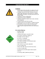
WARNING: 

This 1kg cylinder must be installed in an open plan area or in an enclosed room, with a volume no less than 
20m

3

. If more than 1 gas cylinder containing CO

2

 is present within the same location, the recommended 

ventilated area should be in proportion to the number of gas cylinders stored in that location. 

A ventilated area is a non-enclosed area which could include the kitchen, living room etc.

See gas bottle and MSDS sheet for complete list of warnings.

Summary of Contents for Hydrotap G4 Celsius

Page 1: ...15 V2 00 Page 1 of 28 Hydrotap G4 Celsius Installation Instructions Filtered Boiling Chilled and Chilled Sparkling drinking water with unfiltered Hot and Cold ambient water for residential kitchens Af...

Page 2: ...Page 2 of 28 802149NZ BHA CHA CSHA Installation Instructions Aug 2015 V2 00 Models Model BHA Model CHA Model CSHA...

Page 3: ...ections 12 1 4 Tap installation 13 STEP 2 Check for adequate ventilation Section 2 Ventilation 14 2 1 Cut out details 15 2 3 Cut out procedure 16 STEP 3 Fit the CO2 Gas cylinder CSHA model Section 3 C...

Page 4: ...liance F Check the under counter cupboard supporting the appliance is adequate for the total weight of the appliance when full of water Before Commissioning 1 Check the unit has been installed correct...

Page 5: ...water and a CO2 gas cylinder to carbonate the chilled water The Celsius taps will dispense Boiling or Chilled and Chilled Sparkling water using a rotating handle and deliver a mix of Hot and Cold amb...

Page 6: ...ly qualified tradesperson The power cable and power outlet must be in a safe visible position for connection Venting Sometimes steam and or condensed droplets may discharge through a vent outlet at th...

Page 7: ...nits must never be located near or cleaned with water jets 8 Zenith appliances are not to be exposed to the elements of nature 9 Due to the process of continuous improvement Zenith Heaters reserves th...

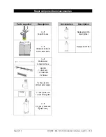
Page 8: ...with hoses 1 off Undersink Unit with air and water filters 1 off Mains water connection hose Vent Kit 1 x Inlet vent 1 x Outlet vent 9 x Screws 1 x Tee piece for ambient water supply 1 x User guide a...

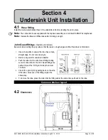
Page 9: ...e product weight when full of water Sufficient space in the cupboard to install all of the undersink units in accordance with these Installation Instructions Refer to technical specification for dimen...

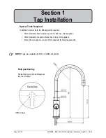
Page 10: ...diameter sheet metal hole punch for sink tops Not supplied 35mm diameter hole saw for timber bench tops Not supplied 42mm AF tube spanner or wrench Not supplied for fixing tap assembly Section 1 Tap I...

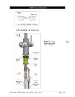
Page 11: ...le in the bench sink top BENCH TOP 1 1 35mm HOT COLD BRAIDED HOSES CHILLED TUBE BRASS WASHER BLACK RUBBER Seal BRASS NUT USB PLUG SPARKLING TUBE JG Y PIECE Note Trim all silicon tubes to minimise any...

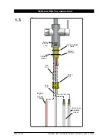
Page 12: ...HA CSHA Installation Instructions Aug 2015 V2 00 HOT COLD BRAIDED HOSES BOILING or CHILLED TUBE BRASS WASHER BLACK RUBBER SEAL BRASS NUT VENT TUBE USB PLUG 1 3 BHA and CHA Tap connections RUBBER Washe...

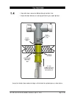
Page 13: ...m hole Ensure the black rubber seal is correctly positioned to give a water tight seal FIT THE RUBBER WASHER BRASS WASHER AND LARGE NUT BLACK RUBBER SEAL 35mm HOLE IN BENCH TOP 1 4 Secure the rubber b...

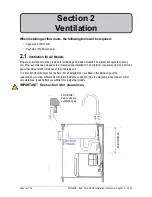
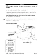
Page 14: ...e and 300mm above of the undersink unit It is important that the 4mm door buffers For all installations are fitted to the inside edge of the cupboard door to allow suficient air circulation inside the...

Page 15: ...or higher the inlet vent See Item B below and silicon buffers need to be fitted If the airflow is still insufficient to maintain normal operating temperatures then the door outlet vent See item D bel...

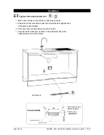
Page 16: ...let vent 1 Mark out and cut the air inlet and door outlet holes as shown 2 Ensure the air inlet vent and air outlet vent are positioned at opposite ends of the same cupboard space 3 Fit the inlet vent...

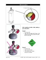
Page 17: ...gas ON rotate the regulator knob clockwise and adjust to 2 7 3 0 bar 270 300kPa The arrow should sit in the green section of the regulator gauge it should not fall in the red or yellow sections 3 4 T...

Page 18: ...tle or after making a gas connection Stage1 1 Turn the gas OFF 2 Using soapy water applied with a sponge or with a brush cover all of the gas joints with a liberal amount of soap suds Stage 2 1 Turn O...

Page 19: ...ut at an angle 2 Remove any swarf or unwanted material 3 Push the tube into the John Guest fitting making sure all connections to the John Guest fittings are pushed in past the O ring to full depth at...

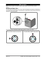
Page 20: ...filter is required 4 3 External Bypass Valve The diverter bypass valve allows the user to choose to have the boiling feed water bypass the internal filter and only be filtered by the external filtrat...

Page 21: ...to the unit RED CLEAR BRAIDED POWER CORD MAINS IN MIXER OUT MIXER IN BOILING OUT BYPASS IN VENT BYPASS OUT USB Note Mains hose length is 750mm Plug and Cord length is 1800mm Position the undersink uni...

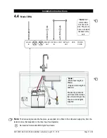
Page 22: ...es theTee piece as supplied to be tted in the cold water supply line from the isolation valve Not supplied to the mixer tap See diagrams Note All silicon tubes must be cut to size They must have a con...

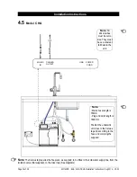
Page 23: ...ons Note Trim all plastic tubed to mini mise any dead leg of water Note The Celsius tap require the Tee piece as supplied to be tted in the cold water supply line from the isolation valve Not supplied...

Page 24: ...Filter Flush Mode is in operation Open the filter access door on the front of the unit and the filter cartridge will be exposed Located to the rear RHS of the cartridge is a flush line approx 600mm lo...

Page 25: ...Turn the stop cock OFF then press Stop to end filter flush mode In order to help preserve our environment we ask that you dispose of this product correctly Please contact your local city council for...

Page 26: ...on Call Zenith Service Condenser sensor Open Internal fault Check ventilation Call Zenith service Heater fuse driver fault Internal fault Call Zenith Service Heater driver fault No hot water Call Zeni...

Page 27: ...802149NZ BHA CHA CSHA Installation Instructions Aug 2015 V2 00 Page 27 of 28 Notes...

Page 28: ...9825 and SA2006 08043 Other patents are in force and patent applications are pending As Zenith policy is one of continuous product improvement changes to specifications may be made without prior notic...

Reviews: