


3
806310NZ v1.06 08.19 CW ChillMaster & EconoMaster
Connect Water
It is the installer’s responsibility to ensure the installation complies with local water
authority regulations and relevant standards.
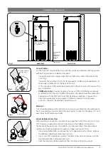
• Connect a cold water supply to the half inch BSP male inlet at the back of the
unit (Fig.2).
• Connect a drain to the 40 mm PVC female outlet (ChillMaster, EconoMaster) or
male outlet (SiteMaster) at the back of the unit.
• Fit the tap spout to the carafe base and tighten the grub screw at the rear of the
tap (if included).
• ChillMaster only:
All valves necessary for use with the ChillMaster are already
assembled within the unit. ChillMaster models incorporate backflow protection
complying with AS3500.1 and no further backflow protection is required. An
integral pressure relief valve protects ChillMaster models from increased
pressures, should a “freezedown” condition arise.
Electrical
A 1.8m flexible cable and 220-240V, 50Hz, 3-pin plug are fitted. Run the cable out of
harm’s way and plug into a standard 10A power outlet. Do not turn the power ‘ON’ until
water flows from the dispense outlet.
Adjust Bubbler Water Flow
When plumbing connections are complete, purge the air from the unit, by turning
‘ON’ the water supply and pressing the button on the bubbler, and rotating
the handle of the carafe tap (if included), until the water flows through without
spluttering. Check connections for leaks and repair any found. Then:
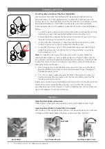
• Use an adjustable shifter to remove the Cartridge Locking Ring Cover. Remove
the Bubbler Operating Button (see Fig.3 & 4).
• Use a small, flat screwdriver to adjust the Water Flow Adjusting Screw until the
desired water flow is achieved (see Fig.5).
• Refit the Operating Button and then the Cartridge Locking Ring Cover.
915
AVG
CHILLMASTER
ONLY:
ADJUSTABLE
12-25 MM
BOTTOM
OF UNIT
350
350
770 790
AVG
COLD WATER INLET:
1/2" BSP MALE
OUTLET:
40MM
PVC
DRAIN
59 111 180
FLOOR LEVEL
REAR VIEW
SIDE VIEW
50
MIN
535
AVG
Fig.2
Cartridge Locking
Ring Cover
Fig.3
Bubbler Button
Fig.4
Water Flow
Adjustment Screw
Fig.5
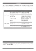
Installation instructions


