DECK MECHANISM ADJUSTMENT
4-13
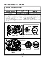
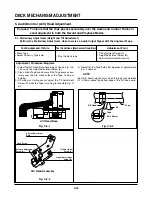
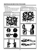
Purpose:To determine if the Mechanism is in the correct position, when a Tape is ejected.
1. Mechanism Alignment position Check
1) Turn the Power S/W on and eject the Cassette by press-
ing the Eject Button.
2) Remove the Top Cover and Top Plate Assembly, visual-
ly check if the Cam Gear Hole is aligned with the
Chassis Hole as below Fig. C-2.
3) If not, rotate the Shaft of the Loading Motor Clockwise or
Counterclockwise until the Alignment is as shown below
in Fig. C-2.
4) Remove the Screw which attaches the Deck Mechanism
and Main Frame, confirm the Cam Gear is aligned with
the Drive Gear as shown below in Fig. C-1 (A).
5) Confirm if the Mode S/W on the Main P.C. Board is
aligned as shown below in Fig. C-1 (B).
6) Remount the Deck Mechanism on the Main P.C. Board
and check each operation.
Cam Gear
Drive Gear
(C)
Mode S/W
(B)
L/D Motor Assembly
Cam Gear
Chassis Hole
Cam Gear Hole
Cam Gear Hole
(A)
(B)
(A')
(B')
Test Equipment/ Fixture
• Blank tape
Test Conditions (Mechanism
Condition)
• Eject Mode (with Cassette ejected)
Check Point
• Mechanism and Mode Switch Position
Fig. C-1
Fig. C-2
CHECK DIAGRAM
BOTTOM VIEW
TOP VIEW
Gear Cam (
o
) and Gear Drive (
o
) groove alignment
Summary of Contents for ABV341 Series
Page 2: ......
Page 36: ...3 34 3 35 2 TU IF CIRCUIT DIAGRAM PB REC...
Page 39: ...3 40 3 41 5 JACK CIRCUIT DIAGRAM...
Page 41: ...3 44 3 45 7 TIMER CIRCUIT DIAGRAM XBV343...
Page 42: ...3 46 3 47 8 TIMER CIRCUIT DIAGRAM XBV342...
Page 45: ...3 52 3 53 PRINTED CIRCUIT DIAGRAMS 1 MAIN P C BOARD LOCATION GUIDE...
Page 65: ...02 12 04 R17149A ZENITH DAP202K 3 80 3 81 6 JACK CIRCUIT DIAGRAM...
Page 70: ...LOCATION GUIDE 3 90 3 91 PRINTED CIRCUIT DIAGRAMS 1 MAIN P C BOARD TOP VIEW...
Page 71: ...LOCATION GUIDE 3 92 3 93 2 MAIN P C BOARD BOTTOM VIEW...
Page 99: ...3 123 3 124 3 AUDIO CIRCUIT DIAGRAM COMBI SCART MTK 03 3 25 SR17447A...
Page 100: ...3 125 3 126 4 AV JACK CIRCUIT DIAGRAM COMBI SCART MTK 03 3 25 SR17446A...
Page 103: ...3 131 3 132 PRINTED CIRCUIT DIAGRAMS 1 MAIN P C BOARD LOCATION GUIDE...
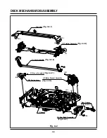
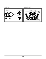
Page 134: ...4 22 GEAR F R GEAR AY P2 P3 F R Lever Tension Base Boss CAM...

