

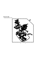


4-4
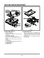
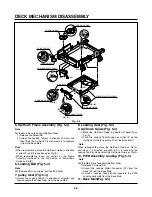
DECK MECHANISM DISASSEMBLY
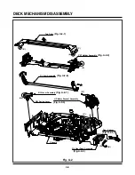
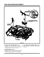
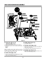
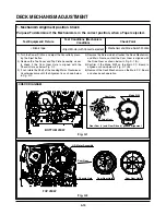
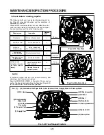
2. Top Plate Assembly (Fig. A-2-1)
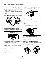
1) Pull the (B) portion of the Top Plate back in direction of
arrow and separate the right side of it.
2) pull the (B’) portion of the Plate Top back in direction of
arrow and separate the left side of it.
(Tools: (-) Flat type screwdrive, anything tool with sharp
point or flat point.)
(1) When reassembling, push the Top Plate on after aligning
the two position (C), (C’) as Fig.
3. CST Holder Assembly (Fig.A-2-2)
1) Move the CST Holder Assembly in direction of arrow and
separate the left side of it first through the (D) position of
the Chassis.
2) Disassemble the right side of the CST Holder Assembly
from each guided hole of the Chassis.
When reassembling, insert the (E) part of the CST Holder
assembly in the (E’) hole of the Chassis first and assemble
the left side of it.
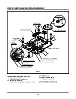
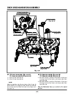
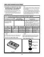
4. Door Opener (Fig.A-2-3)
5. L/D Motor Bracket Assembly
(Fig. A-2-4)
1) Unplug the Connector (C1).
2) Unhook three Hooks (H3, H4, H5) on thr bottom side of
the Chassis, lift up the L/M Bracket Assembly and disas-
emble the L/D Motor Bracket Assembly.
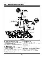
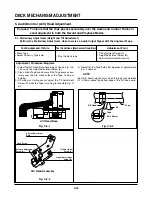
6. F/L Gear Rack (Fig. A-2-5)
1) Move the F/L Gear Assembly Rack in the direction of
arrow (A) and unhook the Hook (H6) pulling back in front.
2) Separate the F/L Rear Rack in direction of arrow (B).
When reassembling, align the Gear part of the Gear F/L
Assembly Rack with the Drive Gear as below Fig.
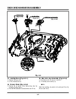
7. F/L Arm Assembly (Fig. A-2-6)
1) Move the F/L Arm Assembly in direction of arrow and
separate the left side of it first.
2) Disassemble the F/L Arm Assembly from each guided
Holes in of the Chassis.
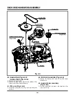
8. S/W Lever Assembly (Fig. A-2-7)
1) Hook the S/W Spring Lever on the Hook (H7) first as
shown below.
2) Unhook the Hook (H8) in the left side of the Chassis and
move the S/W Lever Assembly.
(B')
(C')
(C)
(B)
(D)
Holder assembly CST
Chassis
F/L Gear Rack
Drive Gear
(H8)
(H7)
Chassis
S/W Spring Lever
NOTE
NOTE
(H3)
(H4)
(H5)
Bracket assembly L/M
NOTE
Summary of Contents for ABV341 Series
Page 2: ......
Page 36: ...3 34 3 35 2 TU IF CIRCUIT DIAGRAM PB REC...
Page 39: ...3 40 3 41 5 JACK CIRCUIT DIAGRAM...
Page 41: ...3 44 3 45 7 TIMER CIRCUIT DIAGRAM XBV343...
Page 42: ...3 46 3 47 8 TIMER CIRCUIT DIAGRAM XBV342...
Page 45: ...3 52 3 53 PRINTED CIRCUIT DIAGRAMS 1 MAIN P C BOARD LOCATION GUIDE...
Page 65: ...02 12 04 R17149A ZENITH DAP202K 3 80 3 81 6 JACK CIRCUIT DIAGRAM...
Page 70: ...LOCATION GUIDE 3 90 3 91 PRINTED CIRCUIT DIAGRAMS 1 MAIN P C BOARD TOP VIEW...
Page 71: ...LOCATION GUIDE 3 92 3 93 2 MAIN P C BOARD BOTTOM VIEW...
Page 99: ...3 123 3 124 3 AUDIO CIRCUIT DIAGRAM COMBI SCART MTK 03 3 25 SR17447A...
Page 100: ...3 125 3 126 4 AV JACK CIRCUIT DIAGRAM COMBI SCART MTK 03 3 25 SR17446A...
Page 103: ...3 131 3 132 PRINTED CIRCUIT DIAGRAMS 1 MAIN P C BOARD LOCATION GUIDE...
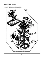
Page 134: ...4 22 GEAR F R GEAR AY P2 P3 F R Lever Tension Base Boss CAM...