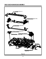
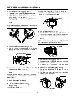
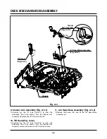
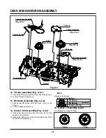
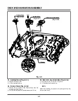
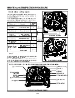
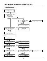
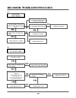
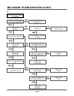
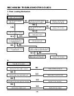
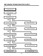

DECK MECHANISM ADJUSTMENT
4-17
Purpose: To obtain compatibility with other VCR (VCP) Models.
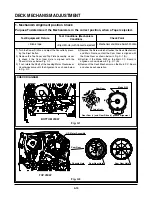
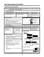
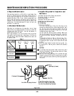
5-2. Confirm that the Tape passes smoothly
between the Take-up Guide and Pinch Roller
(using a Mirror or the naked eye).
1)
After completing Step 5-1. (Preliminary Adjustment),
check that the Tape passes around the Take-up Guide
and Pinch Roller without Folding or Curling at the Top or
Bottom.
(1) If Folding or Curling is observed at the Bottom of
the Take-up Guide then slowly turn the Tilt
Adjustment Screw (C) in the Clockwise direction.
(2) If Folding or Curling is observed at the Top of it then
slowly turn the Tilt Adjustment Screw (C) in the
Counterclockwise direction.
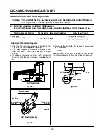
Check the RF Envelope after adjusting the A/C Head, if
the RF Waveform differs from Fig. C-5-4, performs
Precise Adjustment to flat the RF Waveform.
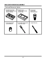
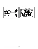
Test Equipment/ Fixture
• Oscilloscope
• Alignment Tape (SP)
• Screw Driver (+) Type 5mm
Connection Point
• Audio output jack
Test Conditions
(Mechanism Condition)
• Play an Alignment Tape
1KHz, 7KHz Sections
Adjustment Point
• Azimuth Adjustment Screw (A)
• Height Adjustment Screw (B)
1) Connect the Probe of the Oscilloscope to the Audio
Output Jack.
2) Alternately adjust the Azimuth Adjustment Screw (A)
and the Tilt Adjustment Screw (C) for Maximum Output
of the 1Khz and 7Khz segments, while maintaining the
flattest Envelope differential between the two
Frequencies.
Adjustment Procedure
5-3. Precise Adjustment (Azimuth adjustment)
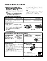
6. X-Value Adjustment
Fig. C-5-4
1KHZ
• Oscilloscope
• Alignment tape (SP only)
• Screw Driver (+) Type 5mm
• CH-1: PB RF Envelope
• CH-2: NTSC: SW 30Hz
PAL: SW 25Hz
• Head Switching Output
Test Point
• RF Envelope Output Test
Point
Test Conditions
(Mechanism Condition)
• Play an Alignment Tape
Adjustment Point
Connection Point
Test Equipment/ Fixture
Adjustment Procedure
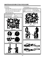
1) Release the Automatic Tracking to run long enough for
Tracking to complete it’s Cycle.
2) Loosen the Fixed Mounting Screw and move the A/C
Head Base Assembly in the direction as shown in the
Diagram to find the center of the peak that allows for the
maximum Waveform Envelope.
This method should allow the 31um Head to be centrally
located over the 58um Tape Track.
3) Tighten the A/C Head Base Assembly mounting Screw.
7KHZ
A:Maximum
B:Maximum
Left
Right
Groove at the
Base A/C
Height Adjustment Screw (B)
Tilt Adjustment Screw (C)
Azimuth Adjustment
Screw (A)
X-Value Adjustment Hole
Fixed Screw
RF ENVELOPE OUTPUT TEST POINT
OSCILLOSCOPE
HEAD SWITCHING OUTPUT TEST POINT
Connection Diagram
Adjustment Diagram
NOTE:
CH-1 CH-2
Summary of Contents for ABV341 Series
Page 2: ......
Page 36: ...3 34 3 35 2 TU IF CIRCUIT DIAGRAM PB REC...
Page 39: ...3 40 3 41 5 JACK CIRCUIT DIAGRAM...
Page 41: ...3 44 3 45 7 TIMER CIRCUIT DIAGRAM XBV343...
Page 42: ...3 46 3 47 8 TIMER CIRCUIT DIAGRAM XBV342...
Page 45: ...3 52 3 53 PRINTED CIRCUIT DIAGRAMS 1 MAIN P C BOARD LOCATION GUIDE...
Page 65: ...02 12 04 R17149A ZENITH DAP202K 3 80 3 81 6 JACK CIRCUIT DIAGRAM...
Page 70: ...LOCATION GUIDE 3 90 3 91 PRINTED CIRCUIT DIAGRAMS 1 MAIN P C BOARD TOP VIEW...
Page 71: ...LOCATION GUIDE 3 92 3 93 2 MAIN P C BOARD BOTTOM VIEW...
Page 99: ...3 123 3 124 3 AUDIO CIRCUIT DIAGRAM COMBI SCART MTK 03 3 25 SR17447A...
Page 100: ...3 125 3 126 4 AV JACK CIRCUIT DIAGRAM COMBI SCART MTK 03 3 25 SR17446A...
Page 103: ...3 131 3 132 PRINTED CIRCUIT DIAGRAMS 1 MAIN P C BOARD LOCATION GUIDE...
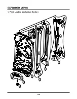
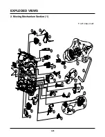
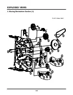
Page 134: ...4 22 GEAR F R GEAR AY P2 P3 F R Lever Tension Base Boss CAM...