


DECK MECHANISM DISASSEMBLY
4-7
Lid Opener
Pinch Arm
Assembly
P4 Base Assembly
T/up Arm
T/up Lever
(A)
(B)
(C)
(C)
(H13)
(B)
(H13)
Chassis
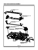
Fig. A-5
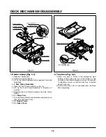
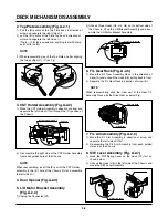
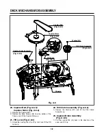
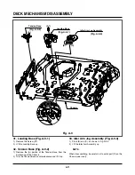
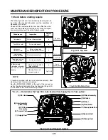
16. P4 Base Assembly (Fig. A-5-1)
1) Carefully pry the (A) portion of the P4 Base Assembly
from the Embossing of the Chassis.
2) Turn the P4 Base Assembly counterclockwise and lift it
up.
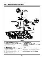
17. Lid Opener (Fig. A-5-2)
1) Carefully pry the (B) portion of the Lid Opener from the
Embossing of the Chassis.
2) Turn the Lid Opener to clockwise direction and lift it up.
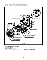
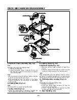
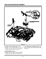
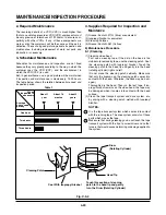
18. Pinch Arm Assembly (Fig. A-5-3)
1) Lift the Pinch Arm Assembly up.
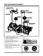
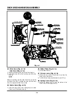
19. T/up (Fig. A-5-4)/
Arm T/up Lever (Fig. A-5-5)
1) Unhook the Hook (H13) of the bottom Chassis and lift the
T/up Lever up.
2) Lift the T/up Arm up.
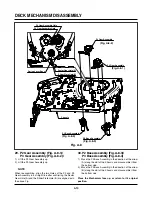
When reassembling, confirm the (C) portion of the Pinch Arm
Assembly is inserted in the Chassis Hole correctly.
Place the Mechanism face down, or up side down.
NOTE
(Fig. A-5-2)
(Fig. A-5-1)
(Fig. A-5-3)
(Fig. A-5-5)
(Fig. A-5-4)
Summary of Contents for ABV341 Series
Page 2: ......
Page 36: ...3 34 3 35 2 TU IF CIRCUIT DIAGRAM PB REC...
Page 39: ...3 40 3 41 5 JACK CIRCUIT DIAGRAM...
Page 41: ...3 44 3 45 7 TIMER CIRCUIT DIAGRAM XBV343...
Page 42: ...3 46 3 47 8 TIMER CIRCUIT DIAGRAM XBV342...
Page 45: ...3 52 3 53 PRINTED CIRCUIT DIAGRAMS 1 MAIN P C BOARD LOCATION GUIDE...
Page 65: ...02 12 04 R17149A ZENITH DAP202K 3 80 3 81 6 JACK CIRCUIT DIAGRAM...
Page 70: ...LOCATION GUIDE 3 90 3 91 PRINTED CIRCUIT DIAGRAMS 1 MAIN P C BOARD TOP VIEW...
Page 71: ...LOCATION GUIDE 3 92 3 93 2 MAIN P C BOARD BOTTOM VIEW...
Page 99: ...3 123 3 124 3 AUDIO CIRCUIT DIAGRAM COMBI SCART MTK 03 3 25 SR17447A...
Page 100: ...3 125 3 126 4 AV JACK CIRCUIT DIAGRAM COMBI SCART MTK 03 3 25 SR17446A...
Page 103: ...3 131 3 132 PRINTED CIRCUIT DIAGRAMS 1 MAIN P C BOARD LOCATION GUIDE...
Page 134: ...4 22 GEAR F R GEAR AY P2 P3 F R Lever Tension Base Boss CAM...