background image

29

28

M U L T I   G A S D E T E C T I O N

7. 

DATA LOGGING

7.6 DOWNLOADING INFORMATION FROM THE MI

The Download function allows you to transfer data from the instrument to the computer.

Follow procedures indicated in 

Section 7.5 Starting the Program

.

Turn on the instrument and allow it to go into normal operating mode.

Click on the Communication menu, then on Download, or simply click on the Download
button on the toolbar of the Main Screen. The Download Data/Instrument Parameters dialog
box appears.

In this dialog box, select Data (for downloading instrument parameters, logged gas
readings, and calibration data) or Instrument Parameters (for downloading instrument
parameters), and click on OK. The following will appear on the screen: “Is the cable
connected and the instrument ready?”

Connect the instrument interface end of the download cable to the port of the instrument.

Click on Yes. The instrument will start to count up. This count also takes place on the
computer screen.

After all data has been transferred, the instrument displays “DATA SENT” and continues to
run in the normal operating mode. When the computer screen displays “Transfer complete”,
click OK.

For downloading instrument parameters, click the Upload/Modify Instrument Parameters button
on the tool bar and the parameters will be displayed in a dialog box. For downloading data,
type your last name, first name, and location, when prompted to do so. Then, click OK.

Wait a moment for the computer to store the information. Now, data from the most recent
download is displayed on the Main Screen and the file relating to this download can be
accessed from the Open dialog box.

WARNING 

Choosing the download instrument parameters option dumps all logged data in the

instrument and the data is not saved in the program.

WARNING 

All fields, including last name, first name, and location, must be entered in order to save the

downloaded data. The maximum length to be entered for last name, first name, and location 

is 14, 14, and 20 alphanumeric characters, respectively.

Downloading at the same date and time for a particular instrument is not allowed. 

For example, if you download data from an instrument having serial number 1234 at 

3:30 p.m. on December 8, 2002, and you try to download again with the same instrument at

the same date and time as above, it will not save any data for this new download.

7. 

DATA LOGGING

7.7 DISPLAYING AND PRINTING DATA
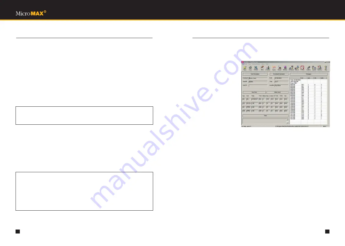
7.7.1 MAIN SCREEN

Information on the Main 
Screen includes the following
(See Figure 7):

• User information 

(employee’s name,
instrument’s serial 
number and user ID)

• Download information 

(date, time, and location 
that data is downloaded)

• Gas data (gas types,

measurement units, peaks,
TWA, and number of alarms)

Note: In user-programmable

immediate alarm mode, the
number of alarms equals to the total number of immediate high and immediate low
alarms for O2, a combustible or toxic gas. In TWA alarm mode, it represents the total
number of instantaneous alarms for a toxic gas, or the total number of immediate high
and immediate low alarms for O2 or 
a combustible gas.

• Alarm levels (immediate low, immediate high, TWA, STEL and instantaneous alarm levels)

• Note relating to a download

• Histogram (logged gas readings)

Note: The histogram is separated into groups. Each time the instrument is turned on, or when

a new day begins during data logging, a new group is created and a new date and time
are displayed for that group.

• When a gas alarm occurs, it indicates so in front of the gas reading in the histogram. 

The letters T, S, I, L, and H are used for alarm indication. In the immediate alarm mode, 
L and H represent immediate low and immediate high alarm, respectively. In the TWA
alarm mode, T, S, and I represent TWA alarm, STEL alarm, and instantaneous alarm,
respectively, for toxic gases only, while L and H represent immediate low and immediate
high alarm, respectively, for O2 or combustible gases. On some occasions, TWA, STEL, 
or instantaneous alarms can occur simultaneously. As a result, any combination of those
three types of alarm would be displayed before the gas reading.

Figure 7

A screenshot of the Mainscreen.

Summary of Contents for Lumidor MicroMAX+

Page 1: ...M U LT I G A S D E T E C T I O N U S E R A N D M A I N T E N A N C E M A N U A L...

Page 2: ...ty claim is valid Zellweger Analytics will repair or replace the defective product free of charge and send it or any replacement back The decision to repair or replace parts shall be determined by Zel...

Page 3: ...6 4 Auto zeroing 24 TABLE OF CONTENTS SUBJECT SECTION PAGE 6 5 Selecting Pump Mode Diffusion Mode 24 6 6 Selecting Immediate Alarm Mode TWA Alarm Mode 24 6 7 Restoring Factory Defaults 25 6 7 Calibra...

Page 4: ...ems Packaging retain for possible future use Instrument with internal rechargeable battery pack Calibration certificate Standard accessories AC battery charger Alkaline battery holder Dust filter 10 f...

Page 5: ...more than an hour after which time a low battery alarm is indicated by two beeps every 15 seconds Low battery alarm will continue for at least half an hour after which instrument will beep continuous...

Page 6: ...eak reading highest toxic or combustible and lowest oxygen levels STEL 15 minute accumulated short term exposure level and TWA 8 hour time weighted average since instrument was last turned on The STEL...

Page 7: ...bypass each setting depress the MODE button To change any setting depress the ON OFF button For example to enter calibration mode depress the ON OFF button when CALIBRATE is displayed See Section 5 Ca...

Page 8: ...to instrument Place hose in area to be sampled 6 Wait two minutes for full response 7 Take readings 8 Retrieve hose and disconnect from instrument Hose lengths up to 100 feet may be used for pretesti...

Page 9: ...sulfides or silicone containing lubricants present in the atmosphere being monitored The safest possible course of action is to expose the sensors to a known concentration test gas before each day s...

Page 10: ...lay CALIBRATING and count down to 0 7 When CAL COMPLETE is displayed observe which sensors are calibrated and displayed below CAL COMPLETE Remove gas and turn off gas flow 8 Depress the ON OFF switch...

Page 11: ...the menu The following are all built in programmable options Date format date time daylight savings time Auto zero during start up sequence TWA alarm on or off Factory default settings Calibration Pu...

Page 12: ...value If the date format is MM DD the first two digits on the left represent the current month and the first digit must be either a 0 or a 1 Let us set the date to September 2 2002 We need 09 to repre...

Page 13: ...efault values for these alarms are pre set See Appendix A Specifications Section I User Programmable High and Low Alarm Set Points at the factory but are user programmable 2 In the TWA alarm mode thre...

Page 14: ...7 DATA LOGGING 7 4 UNINSTALL PROCEDURE For Windows XP users go to Start Control Panel For other Windows users go to Start Settings Control Panel When the Control Panel opens double click the Add Remo...

Page 15: ...first name and location is 14 14 and 20 alphanumeric characters respectively Downloading at the same date and time for a particular instrument is not allowed For example if you download data from an i...

Page 16: ...LOGGING 7 7 2 GRAPH SCREEN Information on the Graph Screen includes the following See Figure 8 User information employee s name instrument s serial number and user ID Download information date time an...

Page 17: ...on readings Fail indicates a calibration failure and N A indicates that a gas sensor is missing To display the calibration history click on the View menu and then on Calibration History or simply clic...

Page 18: ...ption to OFF The factory alarm setting is immediate alarm with values chosen to provide earlier warning than the STEL and TWA settings The immediate high and immediate low alarms are user programmable...

Page 19: ...TING LOCATION The Edit Location function allows you to modify the location for a specific download After a data file is opened click on the Edit menu then on Edit Location or simply click on the Edit...

Page 20: ...rams such as Microsoft Excel Figure 12 A screenshot of the Import File dialog box Figure 13 A screenshot of the Archive Data dialog box 7 DATA LOGGING 7 13 RECOVERING DATA The Recover Data function en...

Page 21: ...tached to the sensor pins 7 Align pins of new sensor with sockets and push down to secure sensor 8 Reconnect gas plate and secure with screw 9 Reconnect battery connector 10 Install case cover and sec...

Page 22: ...bing Part number GFV194 8 9 SAMPLING HOSE MAINTENANCE Check water trap Part number GFV196 the spherical disc located near the middle of the sampling hose periodically to make sure it is clean and unob...

Page 23: ...nd is the only potentiometer trimpot in the instrument 4 Set digital voltmeter to the DC voltage range black lead to test point 12 analog ground and the red lead to test point 10 These test points are...

Page 24: ...ble 90db at 1 foot Visual Large LED bar Flashing display characters APPENDIX A SPECIFICATIONS G GAS RANGES AND RESOLUTION SENSOR INSTRUMENT RANGE RESOLUTION Combustible LEL 0 100 LEL 1 LEL Oxygen O2 0...

Page 25: ...PPM Hydrogen Sulfide H2S 20PPM 15PPM 10PPM Sulfur Dioxide SO2 10 0PPM 5 0PPM 2 0PPM Phosphine PH3 5 0PPM 1 0PPM 0 3PPM Ammonia NH3 50PPM 35PPM 25PPM Chlorine CL2 5 0PPM 1 0PPM 0 5PPM Chlorine Dioxide...

Page 26: ...10 000 1 Ethylene 500 15 Carbon Monoxide 100 7 Carbon Dioxide 10 000 3 Hydrogen Sulfide 25 25 APPENDIX A SPECIFICATIONS SULPHUR DIOXIDE GAS CONCENTRATION PPM TYPICAL RESPONSE PPM Carbon Monoxide 300pp...

Page 27: ...ermane 1 0 Hydrogen Fluoride 4 0 Alcohols 1000 0 NOTE 1 Short term in minute range APPENDIX A SPECIFICATIONS HYDROGEN CYANIDE GAS CONCENTRATION PPM TYPICAL RESPONSE PPM Hydrogen Sulfide 10 40 Sulfur D...

Page 28: ...Hydrogen Fluoride 3 0 Alcohols 1000 0 Ozone 0 1 0 03 Note Short gas exposure in minute range APPENDIX A SPECIFICATIONS CHLORINE GAS CONCENTRATION PPM TYPICAL RESPONSE PPM Hydrogen Sulfide 10 Neg 0 3 N...

Page 29: ...carbons 10 000 0 Ammonia 30 0 Ozone 1 0 7 Diborane 0 1 0 Arsine 0 1 0 Germane 1 0 Fluorine 3 0 Alcohols 1000 0 Nitrogen Monoxide 100 0 COMBO TOX CO H2S GAS CONCENTRATION PPM TYPICAL RESPONSE PPM Hydro...

Page 30: ...rounding the instrument Refer to Section 8 8 Pump Inlet Filter Replacement for maintenance DO NOT USE non standard sampling tube or fittings Storage Temperature Range 20 degrees C to 50 degrees C 4 de...

Page 31: ...0 P11 52 B Note Max time from Turn On to Ready does not exceed 80 seconds APPENDIX C MODE SEQUENCE STANDARD SEQUENCE DISPLAY LED SPEAKER TO CLEAR PEAK VALUES TO ENTER USER SETUP BEEP 3 BEEPS BEEP BEEP...

Page 32: ...Sequence Standard Mode for how to enter User Set up Mode A DISPLAY LED SPEAKER DEFAULT ON BEEP PUMP STATUS ON APPENDIX D MODE SEQUENCE USER SET UP MODE CALIBRATION LED SPEAKER BEEP 3 BEEPS BEEP OX LEL...

Page 33: ...25 PURGING PLEASE WAIT OX LEL C0 H2S APPLY GAS AUTOMATIC MEMORY CLEAR AFTER PURGING CALIBRATION COMPLETE ONLY SHOWS GASES CALIBRATED NORMAL OPERATING MODE ON OFF YES NO B APPENDIX D MODE SEQUENCE USER...

Page 34: ...P 08 49 B B B FLASH CONTINUOUS HORN FLASH LONG CONTINUOUS BEEPS FLASH LOW GAS ALARM LOW FLOW ALARM 3 BEEPS OX LEL C0 H2S 20 9 0 0 0 DANGER P 08 49 B 3 BEEPS FLASH HIGH GAS ALARM APPENDIX E ALARMS MOD...

Page 35: ...carrying case MCC215A MPRO KIT 1 MINI Kit containing 34 liter calibration gas cylinder GFV243 CH4 CO H2S balance air regulator tubing and water resistant carrying case MCC210A MPRO KIT 2 Kit containi...

Page 36: ...d by the foot GFV256 Tygon hose tubing sold by the foot GFV196 Replacement water filter APPENDIX I REPLACEMENT PARTS PART NO DESCRIPTION 20HFC Replacement dust filter MPLUS DATALOG Data logging softwa...

Page 37: ...first calibration gas is GFV123 the second calibration gas is either GFV 213 58 Liters or GFV 250 34 Liters b MPLUS 4ABCH O2 LEL CO and SO2 Follow the procedure in Section 5 2 Calibration Procedure w...

Page 38: ...M U LT I G A S D E T E C T I O N 9021 Zellweger Analytics 400 Sawgrass Corporate Pkwy Suite 100 Sunrise FL 33325 Tel 1 954 514 2700 Toll free 1 800 538 0363 Fax 1 954 514 2784 MAN MPLUS REV A 0...

Reviews: