Zektor MAS7.1 User Manual Download Page 18

2

MAS7.1 Component Video Switch 

MAS7.1 Component Video Switch

Rear Panel IR Control

The rear panel jack labeled "IR-IN" allows the MAS7.1 to be con-
trolled by hardwired IR controllers. 

To enable/disable the rear panel IR jack , see the section entitled: 

"Control Functions"

.

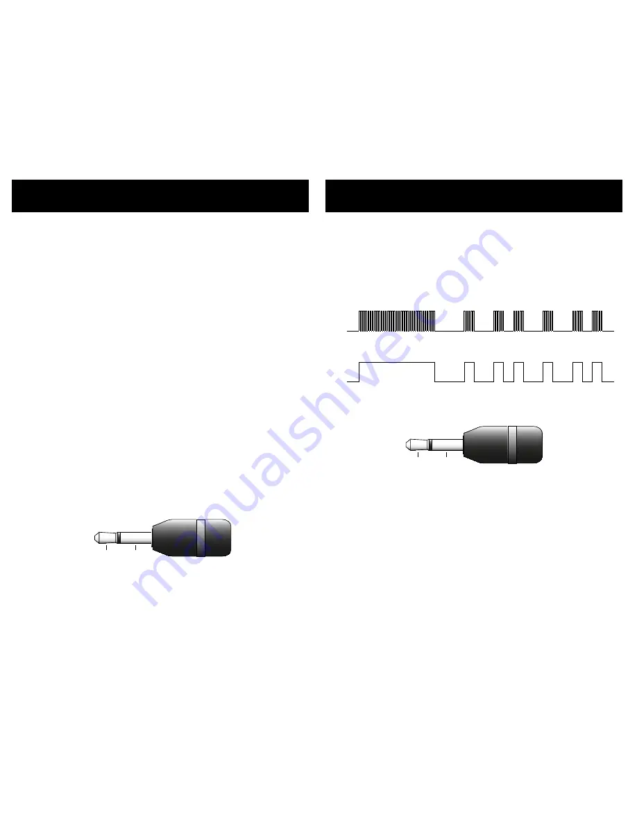
The IR signal can be either modulated or unmodulated with a modu-
lation frequenc y ranging from 0KHz to 500KHz.

30KHz to 500KHz

3V to 15V

0V

MODULATED SIGNAL


UNMODULATED SIGNAL

3V to 15V

0V

And uses a standard 1/" (.5mm) mini-plug:

SLEEVE

TIP

The voltage level is bi- directional and fully opto -isolated. I t doesn' t 
matter which way you connect your voltage source across the tip 
and sleeve of the connector. Neither side of the IR-jack is grounded, 
and either the tip or the sleeve can be connected to ground without 
the possibility of ground loops.

The signal voltage can range from +V to +15V or from -V to -15V.

The IR jack recognizes the same IR codes as the front panel IR sen-
sor. If the MAS7.1 is taught new codes, these new codes will become 
the new codes recognized by the IR jack .

Note:   The IR control jack option is mutually exclusive with 12V 

On/Off control option (they use the same jack!).Only one 
of these options can be enabled at a time.

12V On / Off Control

The rear panel jack labeled "IR-IN", when not being used as an IR 
Jack , can allow the MAS7.1 to be turned on and off using a 12V con-
trol voltage.

To enable/disable the 12V On/O ff control functions, see the section 
entitled: 

"Control Functions"

.

By enabling the 12V On/O ff control option, the MAS7.1 will turn 
itself on whenever the voltage going into the IR-IN jack goes from 
LOW to HIGH, and it will turn itself off whenever the voltage goes 
from HIGH to LOW.

The MAS7.1 only looks at transitions on the IR-IN jack . For instance if 
it detects a LOW to HIGH transition it will turn itself on. The user can 
then use the power switch to turn off the MAS7.1. After which the   
voltage on the IR-IN jack must go from HIGH to LOW and then back 
to HIGH, to once again turn on the MAS7.1.

The voltage level is bi- directional and fully opto -isolated. I t doesn' t 
matter which way you connect your voltage source across the tip 
and sleeve of the connector. Neither side of the IR-jack is grounded, 
and either the tip or the sleeve can be connected to ground without 
the possibility of ground loops.

A HIGH level is any voltage from +V to +15V, or any voltage from   
-V to -15V.

A LOW level is any voltage between -0.2V and +0.2V.

All levels between these two levels is undefined.

SLEEVE

TIP

Note:   The 12V On/Off control option is mutually exclusive with 

IR Control jack option (they use the same jack!).Only one 
of these options can be enabled at a time.

Summary of Contents for MAS7.1

Page 1: ...1 2 3 S1 S2 S3 SYNC Rev 2 07 17 2007 Multichannel Audio HDMI Switch MAS7 1 Home Theater Solutions...

Page 2: ...s Manual If anything is missing please get in touch with us as soon as possible so that we can correct the situation 1 2 3 4 What s Inside Contents What s Inside 1 An Overview of the MAS7 1 3 Rear Pan...

Page 3: ...ll switch only the 5 1 Multi channel audio paths LF RF SUB CEN LR RR while pressing a Secondary button S1 S3 will switch the Stereo Audio paths L R the Digital audio and the HDMI signal However this d...

Page 4: ...Audio Inputs and Output HDMI Inputs and Output Stereo Audio Inputs Stereo Audio Outputs Optical TOSlink Digital Audio Inputs and Output Hardwired IR Jack input RS 232 Control Port Power Supply Connect...

Page 5: ...Press the Power Toggle button again to re select the previously selected input Synchronizing Primary and Secondary Switches When the SYNC LED is lit the primary and secondary selec tions will switch a...

Page 6: ...the section of the remote controlled labeled MAS7 for controlling the MAS7 1 The other sections are used to control other Zektor products Each button on the remote functions the same as the front pane...

Page 7: ...odes On your remote control press the following buttons in the following order Power 1 2 3 4 5 6 0 The front panel LED s will sequence as each button is pressed and the IR LED will flash for each butt...

Page 8: ...most remotes however there are a few exceptions Some technical reasons for not working with some re motes are The remote may be using a carrier frequency outside the range of the MAS7 1 34KHz to 42KH...

Page 9: ...e primary inputs Sequence Sec Sequence secondary inputs Sync On Turn on SYNC LED Sync Off Turn off SYNC LED Breakaway Video Sets video breakaway mode The new codes are learned in the above order for i...

Page 10: ...If the 1 LED is lit then front panel lights are always off If the 2 LED is lit then front panel is always dim If the 3 LED is lit then front panel is always bright If the S1 LED is lit then front pane...

Page 11: ...bright and dim settings Step 5 Adjust Front Panel Intensities Use the S2 button to decrease the intensity of the front panel lights Use the S3 button to increase the intensity of the front panel light...

Page 12: ...y mode It is possible to change the initial power on behavior of the MAS7 1 To change the initial power on defaults Step 1 Setup the MAS7 1 to your preferred power on state Use the front panel buttons...

Page 13: ...nel buttons Use S1 to enable disable IR control Use S2 to enable disable 12V On Off control Note 1 The IR Jack and 12V On Off control functions are mutu ally exclusive They use the same jack Enabling...

Page 14: ...lows No LEDs lit 0 sec delay One left justified LED 20ms delay Two left justified LEDs 50 ms delay Three left justified LEDs 100ms delay Two right justified LEDs 200ms delay One right justified LED 50...

Page 15: ...Mode Press the S3 button to enter the Primary Secondary Map ping Setup Mode Step 3 Select new Primary Secondary Mappings A lit LED indicates a channel is mapped to the Primary switch an unlit LED ind...

Page 16: ...ke to reset your MAS7 1 back to its factory default condition this is easily done Step 1 Reset All Parameters to Factory Defaults First press and hold the Power button While continuing to hold the Pow...

Page 17: ...ver all features of the MAS7 1 All front panel functions supported Full notification of state changes The ability to disable the front panel and still have front panel button presses sent to the seria...

Page 18: ...f Control The rear panel jack labeled IR IN when not being used as an IR Jack can allow the MAS7 1 to be turned on and off using a 12V con trol voltage To enable disable the 12V On Off control functio...

Page 19: ...6 mS The following are the factory default codes used by the MAS7 1 Handheld Remote Codes Function 807D8877 Power Toggle 807D40BF 1 Button 807D609F 2 Button 807D50AF 3 Button 807D48B7 S1 Button 807D68...

Page 20: ...ndby 2W On 4 5W Typical 90 120VAC 60Hz 90 264VAC 47 63Hz Wall Mount 9V 500ma U L Listed Center connection is Rack Mountable 17 W x 6 5 D x 1 75 H Two Year Parts and Labor Specifications Specifications...

Page 21: ...ip under normal use and service for two years from the origi nal date of purchase ZEKTOR at its option shall repair or replace the defective unit covered by this warranty In order to keep this warrant...

Page 22: ...40 MAS7 1 Component Video Switch 41 MAS7 1 Component Video Switch This page intentionally left nearly blank This page intentionally left nearly blank...

Page 23: ...Z E K T O R 12675 Danielson Ct Suite 401 Poway CA 92064 858 748 8250 www zektor com...

Reviews: