


2
MAS7.1 Component Video Switch
25
MAS7.1 Component Video Switch
Changing Switching Delays
The MAS7.1 allows adjusting the switching delay times, for Multi-
channel Audio, Stereo Audio, Digital Audio and HDMI, all indepen-
dent of each other.
To adjust the Audio / Video switching delays...
Step 1: Place the MAS7.1 into the Setup Mode
The MAS7.1 is placed into the setup mode by pressing and
holding the Power button for about seconds.
Step 2: Enter the Switching Delay Setup Mode
Press the 'S2' button to enter the Switching Delay Setup
Mode.
The LEDs indicate the mute delay, if there are no LEDs lit,
then there is no delay.
When SYNC LED is lit, then LEDs 1, 2 and indicate the
current HDMI delay, and S1, S2 and S, indicate the Digital
Audio mute delay.
When SYNC LED is off, then LEDs 1, 2 and indicate the cur-
rent Multi- channel Audio delay, and S1, S2 and S, indicate
the Stereo Audio delay.
The delay times are represented by the number and posi-
tion of the lit LEDs, as follows:
No LEDs lit
= 0 sec delay.
•
One left justified LED
= 20ms delay.
••
Two left justified LEDs
= 50 ms delay.
•••
Three left justified LEDs
= 100ms delay.
••
Two right justified LEDs
= 200ms delay.
•
One right justified LED
= 500ms delay.
Step 3: Adjust Switching Delay Times
The 'SYNC' button toggles between the HDMI/Digital Audio
delay settings and the Multi- channel/Stereo Audio delay
settings.
The '1' and 'S1' buttons decrease delay times, and the ''
and 'S' buttons increase delay times.
Press the Power button to save new settings and exit.
Note:
The new settings are saved in non-volatile memor y and
are not affec ted by a power failure.
•
•
•
•
•
•
•
•
•
1 2 3 S1 S2 S3 SYNC
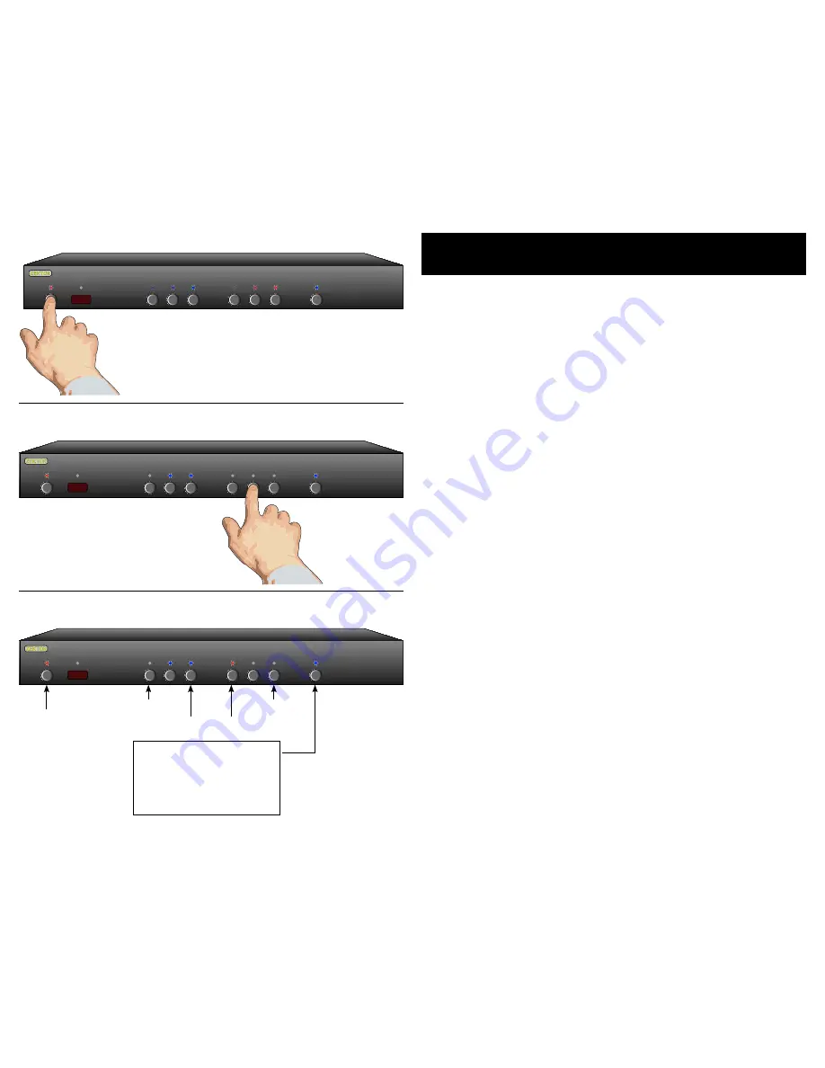
Step 1: Place the MAS7.1 into the Setup Mode
Press and hold the Power Button until the
display goes wild. (About seconds.)
Step 2: Enter the Switching Delay Setup Mode.
1 2 3 S1 S2 S3 SYNC
After pressing 'S2', the standby
LED continues to flash, and the
front panel will display the cur-
rent delay settings.
Step 3: Adjust Switching Delay Times
1 2 3 S1 S2 S3 SYNC
LED is lit when adjusting
HDMI/Digital Audio delays
LED is unlit when adjusting
Multi-channel and Stereo
Audio, delays
Exit
Decrease delay
Increase delay
Increase delay
Decrease delay


