background image

26

HDVI5 Component Video Switch 

2

HDVI5 Component Video Switch

K.I.S.S.™ (Keep It Simple Serial!™)

Zektor ’s exclusive K .I.S.S.™ (Keep I t Simple Serial™) protocol was de -
signed by engineers who have been controlling RS-22 devices for 
most of their careers and understand the pitfalls of a badly designed 
protocol.

A few features of the K.I.S.S.™ protocol are:

A simple and logically consistent command struc ture.
Fully bi- direc tional operations and can operated in both 

a Master Slave mode (only responds when spoken to), or 

in an Asynchronous mode (state changes are sent as they 

occur).
All commands and responses can optionally use a checksum 

or a CRC-8 checkcode to insure reliable communications.
A command will always generate a response! There are no 

“timeout ” states as par t of the protocol. A timeout will al-

ways indicate some type of physical connec tion error (loose 

cable, ex treme noise, etc.).
Commands and responses have been designed for simple 

parsing in any language.
Easy to test using a terminal, or terminal emulation soft-

ware. (Hyper term, SecureCRT, etc.)

A few features of the HDVI5 command set are:

A full featured command set that goes far beyond simple 

front panel control operations! Allows full control over 

all


features of the HDVI5.
Full notification of state changes. 
The ability to disable the front panel, and still have front 

panel button presses sent to the serial por t.
The ability to read all IR codes sent to the HDVI5 by any re -

mote, even those not used by the HDVI5. Use the HDVI5 to 

add IR control to any projec t!

Many more features, too numerous to list here...

For a full description of K .I.S.S.™ and a list of the commands sup -
por ted by the HDVI5, download the HDVI5 supplemental manual at:

www.zektor.com/HDVI5/downloads.htm


The RS-22 on the HDVI5 is the same format as a PC-modem, and 
uses the same type cable as a serial modem would, which is a stan-
dard straight through cable. Do not use a cable that is marked as a 
“Null Modem” cable.

The HDVI5 can also be used with any USB to RS-22 conversion 
cable, these are all typically straight through cables.

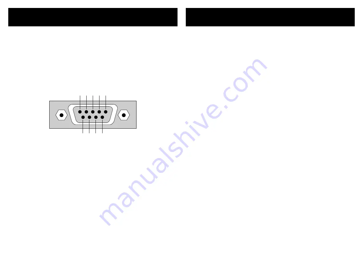
The RS-22 por t is a female type DE- connec tor (sometimes mistak-
enly referred to as a DB- connec tor) with the following pinout:

5   4   3   2   1

9   8   7   6

Pin definitions:

1  -  No  Con ne ct  


6  -  No  Con ne ct

2  -  TX  


7  -  No  Con ne ct

3  -  RX  


8  -  No  Con ne ct

4  -  No  Con ne ct  


9  -  No  Con ne ct

5  -  GND

The por t settings used by the HDVI5 are:

Ba ud rat e:  

96 00

Da ta  Bi ts:  

8

St op  Bi ts:  

1

Pa ri ty:    

NO NE

The communications protocol used is Zektor ’s exclusive K .I.S.S.™ 
(Keep I t Simple Serial™) protocol.

The RS-232 Port

All manuals and user guides at all-guides.com

Summary of Contents for HDVI5

Page 1: ...me Theater Switches Digital Video Component Video Multichannel Audio Rev 1 02 28 2006 Digital Video Switch Picture of HDVI5 HDVI5 PRELIM INARY W I P All manuals and user guides at all guides com l l g...

Page 2: ...odule This User s Manual If anything is missing please get in touch with us as soon as possible so that we can correct the situation 1 2 3 What s Inside Contents What s Inside 1 An Overview of the HDV...

Page 3: ...both a Coax and an Optical connection Only one of the two types of inputs can be active at any time The HDVI5 will auto select between the two types of signals If a signal is supplied to both the Coa...

Page 4: ...s and release the Power Toggle button The channel LEDs will all go blank and the standby LED will light up Press the Power Toggle button again to re select the previously selected input Audio Video Br...

Page 5: ...DVI5 Using any remote to operate the HDVI5 is a simple mat ter of pairing up the HDVI5 with the remote The remote doesn t have to be a universal remote although it can be any remote from an old TV or...

Page 6: ...r new IR codes to be sent from your remote control Step 3 Teach the HDVI5 your new remote control codes On your remote control press the following buttons in the following order Power 1 2 3 4 5 0 8 9...

Page 7: ...en front panel lights are always off If 2 s blue LED is lit then front panel is always dim If 3 s blue LED is lit then front panel is always bright If 4 s blue LED is lit then front panel lights auto...

Page 8: ...on to toggle between bright and dim settings Step 5 Adjust Front Panel Intensities Use the A1 button to decrease the intensity of the front panel lights Use the A2 button to increase the intensity of...

Page 9: ...possible to change the power on behavior of the HDVI5 To change the power on defaults Step 1 Setup the HDVI5 to your preferred power on state Use the front panel buttons to setup the HDVI5 to the oper...

Page 10: ...ontrol Note 1 When disabling the IR Jack and IR Sensor the actual hardware is disabled Whereas IR Control enables disables whether the HDVI5 responds to IR signals re ceived The difference mostly conc...

Page 11: ...s a 100ms second delay Two lit LEDs indicates a 200ms second delay Three lit LEDs indicates a 1 2 second delay Four lit LEDs indicates a 1 second delay Five lit LEDs indicates a 2 second delay Step 3...

Page 12: ...red input and hold the button for 4 seconds until the HDVI5 enters the Cable Length Adj Mode Step 2 Enter the Cable Length Adj Mode Use the A1 and A2 buttons to tune cable length A1 adjusts for shorte...

Page 13: ...allow them to HSJitter Some non compliant sources can generate horizontal jit ter causing the screen to jump back and forth horizontally This set ting can eliminate this problem on all standard resolu...

Page 14: ...ored to their factory programmed values 3 Resetting to Factory Defaults If for whatever reason you d like to reset your HDVI5 back to its fac tory default condition this is easily done Step 1 Reset Al...

Page 15: ...llows full control over all features of the HDVI5 Full notification of state changes The ability to disable the front panel and still have front panel button presses sent to the serial port The abilit...

Page 16: ...V to 12V 0V MODULATED SIGNAL UNMODULATED SIGNAL 3V to 12V 0V And uses a standard 1 8 3 5mm mini plug GND SIGNAL 3V to 12V The signal voltage can range from 3V to 12V with a nominal value of 5V recomme...

Page 17: ...ll Single Link DVI HDMI modes supported Both DVI and HDMI HDCP modes supported Fully supports all HDMI Audio modes 640x480p through 1920x1200p All Single Link PC resolutions supported 5 Coax 5 Optical...

Page 18: ...service for two years from the origi nal date of purchase ZEKTOR at its option shall repair or replace the defective unit covered by this warranty In order to keep this warranty in effect the product...

Page 19: ...Z E K T O R Z E K T O R 12675 Danielson Ct Suite 401 Poway CA 92064 858 748 8250 www zektor com All manuals and user guides at all guides com...

Reviews: