background image


23 – LSM 880 Training Guide 

Understanding Image Quality 

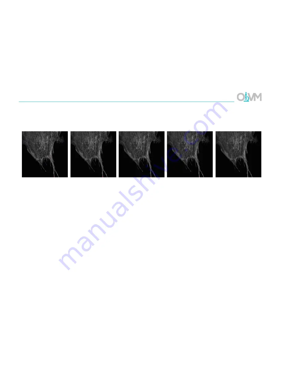
Depending on the quality of the signal level in the final optimized image, you may find that the image is somewhat noisy.  To 

compensate for this, the system has averaging functions in the ‘Acquisition Mode’ tab (page 14) that can be used to clean up the 

image.  Simply select the rate of averaging (1, 2, 4, 8, or 16x) and rescan. 

Note:  Averaging signal will increase the acquisition time by the factor of averaging.  For example, a 4x average will increase the 

time to scan the image by a factor of 4. 


No Averaging 

2x Averaging 

4x Averaging 

8x Averaging 

16x Averaging 

Summary of Contents for LSM 880 with AiryScan FAST

Page 1: ...Training Guide for Carl Zeiss LSM 880 with AiryScan FAST ZEN 2 3 Optical Imaging Vital Microscopy Core Baylor College of Medicine 2018...

Page 2: ...n ON both Systems PC and Components switches By default the Lasers key located on the side of the remote paddle should always be in the ON state but please verify 3 Turn ON HXP 120V epi fluorescence l...

Page 3: ...uble click ZEN Black icon to start software Note Be sure to use Zen Black instead of ZEN Blue Icon above is for Black version 6 When software has started you will be presented with a login screen Sele...

Page 4: ...es of tools for sample observation image acquisition image processing and system maintenance Image Display This area is where each newly captured image will appear Settings here allow the user to cont...

Page 5: ...5 LSM 880 Training Guide Getting Started with ZEN 2 3...

Page 6: ...ue toolbar labeled Laser and select Argon from the laser list 3 Toggle Power button from Off to On Note This laser requires a 5 minute warm up time Once you select On the system will count down from 3...

Page 7: ...visualization in the eyepieces Green generic green filter set Red generic red filter set Blue generic blue filter set TL DIC transmitted light All Closed turn off all light sources Note These shortcut...

Page 8: ...Microscope 4 Via the microscope eyepieces visualize your sample and adjust the focus Z and stage position X Y accordingly 5 Once a suitable location is found click ALL CLOSED from shortcuts 3 6 Select...

Page 9: ...ode is the fastest approach many fluorophore combinations will exhibit enough spectral overlap to be able to detect unwanted signal from neighboring fluorophores using this method This phenomenon is k...

Page 10: ...cks apart from laser line and detector choice All other settings must remain the same This limits you to a maximum of 4 fluorescence channels plus one transmission image with this mode 2 Frame track s...

Page 11: ...elength fluorophore Alexa 568 in this case on Track 1 Note By default ZEN will start with one track Track 1 To add additional tracks click the button next to the track list 3 Click Visible Light to op...

Page 12: ...velength fluorophore In our example we will be using a sequential scan with Alexa 568 and Alexa 488 so Ch1 or ChS1 will be used for the Alexa 488 signal and Ch2 will collect the Alexa 568 8 Define upp...

Page 13: ...ling frequency can be quickly selected with the Optimal button Scan Speed overall speed of the scan during acquisition Reports pixel dwell time and total scan time Increasing dwell time slowing down t...

Page 14: ...thickness Reports section thickness and pinhole diameter Gain Master controls the analog amplification voltage for the PMT in Volts The higher this value the more sensitive the detector becomes to the...

Page 15: ...here your signal is the highest but your axial resolution is at its lowest As you reduce the aperture diameter you are increasing your Z resolution but reducing your signal level This is a reasonable...

Page 16: ...Range Indicator place a check in the box The Range Indicator LUT assigns red pixels to areas in the image that are overexposed and blue pixels to background areas that are underexposed Note The Range...

Page 17: ...mately prevent any unnecessary photobleaching of other channels 2 Click Live to start scanning 3 Turn on Range Indicator LUT as shown on the previous page 4 Deselect laser checkbox for the active trac...

Page 18: ...trast have the brightest areas fall just below overexposure red and the background areas fall just above underexposure limit blue In a properly balanced image you should see no red or blue pixels with...

Page 19: ...ion but increases signal level reported to the detector Closing this aperture will reduce the signal level but increase axial resolution Laser Intensity The intensity of the laser illumination source...

Page 20: ...erture to 1 AU You can certainly close the confocal aperture below this value and continue to improve resolution just understand that below 1 AU you will lose signal level at an exponential rate Conve...

Page 21: ...unforeseen effects on the sample For most lasers on this microscope we recommend laser power settings between 1 and 5 to start It is recommended to start as low as you can possibly go and still get a...

Page 22: ...s here but they are readily apparent when using a gain value 500V Below 500V it is very difficult to detect much noise at faster scan speeds however when using the detector above this value you will f...

Page 23: ...system has averaging functions in the Acquisition Mode tab page 14 that can be used to clean up the image Simply select the rate of averaging 1 2 4 8 or 16x and rescan Note Averaging signal will incre...

Page 24: ...dialog click Set First to mark the start position 5 While continuing to scan focus the drive in the opposite direction until your sample comes back into focus then continue focusing until it goes out...

Page 25: ...idimensional Acquisition settings 2 To calculate the required number of cycles divide the duration you require for the series by the interval For example if we wish to collect for 6 hours in total wit...

Page 26: ...stage position Here you can manually define the number of tiles in X and Y along with the Overlap to define the tile area Bounding grid creates a tile scan by defining the boundaries of the section Co...

Page 27: ...m the list of open images on the right hand side of the screen 2 Click to save the image 3 Navigate to the local D and select the folder with your name If there is not one please create one 4 Choose t...

Page 28: ...ose ZEN 2 3 application Note When prompted turn off the lasers change the state of each laser to OFF 3 Shut down Windows operating system Note Please wait for operating system to shut down completely...

Page 29: ...the blue dialog labeled Imaging Setup 2 Begin with the longest wavelength fluorophore Alexa 568 in this case on Track 1 Note By default ZEN will start with one track Track 1 To add additional tracks c...

Page 30: ...h can slow the system down When choosing this filter try to choose the best filter that matches two of your fluorophores In our example we would want to choose a filter for both the Alexa 488 and the...

Page 31: ...olbar expand the blue Channels dialog 2 Click SR airyscan mode Note This mode will automatically set our pinhole and ensure our Optimal features are set appropriately 3 Start Live scan 4 Turn on range...

Page 32: ...o to Acquisition Mode and under Frame Size click Optimal Note Using the Optimal feature is essential for sampling the field of view correctly for AiryScan The raw data needs to be sampled at Nyquist 2...

Page 33: ...re the image has enough detail and contrast please do not attempt to use channels where the fluorescence is diffuse 1 Go to Maintain tab in the main toolbar and undock the Airyscan dialog Place this s...

Page 34: ...34 LSM 880 Training Guide Aligning AiryScan...

Page 35: ...AiryScan detector view shows evenly illuminated array as shown in example image Note Initially you may see the quality and status readout Out of Range or Bad while the alignment is running These are...

Page 36: ...it to generate the final image 1 Go to Processing tab and select Airyscan Processing from method list 2 Select previously scanned image as Input image 3 To start select strength to Auto and select 2D...

Page 37: ...To add additional tracks click the button next to the track list 4 Click Visible Light to open the laser dialog 5 Select the laser line you wish to use for this track 6 Set laser power slider this is...

Page 38: ...which can slow the system down When choosing this filter try to choose the best filter that matches two of your fluorophores In our example we would want to choose a filter for both the Alexa 488 and...

Page 39: ...Note The sampling rate is broken down into 4 options SR 2x sampling Nyquist choose this mode for the best possible resolution OPT 1x sampling equivalent to confocal choose this option for image quali...

Page 40: ...base LSM The first value is the percentage laser power for the FAST mode and is equivalent to the second value in the LSM mode For example 2 of 561nm in FAST mode is equivalent to 0 25 in LSM mode 3...

Page 41: ...41 LSM 880 Training Guide Using AiryScan FAST 9 Snap Image 10 Processing AiryScan FAST data see page 36 for procedure...

Reviews: