background image

RCF Microscopy Manual 


5/2/2017 

Authors Cory Nook and Chaowei Shang 


Page 4 of 19 


Once turned on, the lamp should remain on 
for a minimum of 30 minutes. Do not turn the 
lamp off if another user is scheduled within 2 
hours after your session. 


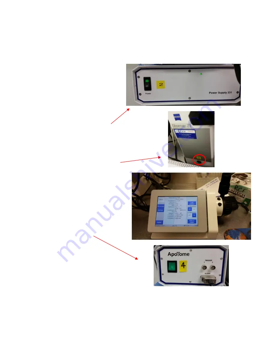
Secondly, turn on the Power Supply 2 by 
flipping the switch which will have a green 
light turn on.  


Third, you will need to go in between the 
microscope and the power supplies to press 
the button below the yellow sticker with the 
number 3. See image to the right.  This will 
turn on the TFT Display, shown adjacently, and 
please wait for this display to fully load before 
proceeding.  


Lastly, turn on the Apotome power supply 
labeled with a yellow 4 sticker.  


The computer should be on and logged in with your LSUHSC ID and password. Make sure the domain is set to 
LSUMC-MASTER, selected from the drop-down menu. If you only wish to access documents/files, then login 
and do not turn on the mercury lamp power supply or the other buttons. Please indicate this on the sign in 
sheet.  


Summary of Contents for AxioObserver

Page 1: ...Zeiss AxioObserver with ApoTome Quick Start User Guide AxioVision4 8 LSU Health Sciences Center Shreveport Research Core Facility RCF Microscopy...

Page 2: ...software Page 8 4 1 Experiment settings Page 9 4 2 Apotome Settings Page 10 4 3 Channel Creation Page 11 4 4 Setting Exposure Page 12 5 Acquiring and saving an experiment Page 13 5 1 Acquire Page 13...

Page 3: ...as the 10x objective in place This is a safety precaution If the 10x objective is not in place please clean the current objective and manually switch it to the 10x objective To manually switch objecti...

Page 4: ...supplies to press the button below the yellow sticker with the number 3 See image to the right This will turn on the TFT Display shown adjacently and please wait for this display to fully load before...

Page 5: ...Y direction of the stage The degree of which the stage will change will depend on which objective is in the light path The image to the right displays the Home screen and we will go over useful infor...

Page 6: ...if the Control icon on the sidebar is white and not blue An icon is selected if it is white and not selected icons will appear blue as shown to the right The Objectives displayed tell you which one i...

Page 7: ...bleed through 31 AF 568 EX 565 30 EM 620 60 for Cy 3 Texas Red 17 AF 488 EX 485 20 EM 540 25 for GFP FITC and prevents red emission bleed through 50 Cy 5 EX 640 30 EM 690 50 for Cy 5 and far red dyes...

Page 8: ...kets along the track The template will hold a variety of shapes If you need a multi well plate template please ask staff Start with DAPI to find and focus on your sample Be aware that fluorescence lig...

Page 9: ...ws a more detailed view of the options in the Workarea The Microscope selection allows you to adjust parts of the microscope similar to the options in the TFT display All options with a plus sign to t...

Page 10: ...the ApoTome from the microscope turn off its power supply first Labeled 4 which allows the grid to return to its original position then turn in back ON before you pull it part or all of the way out F...

Page 11: ...ull up the following window Next to the Experiment tab click on the blue circle icon to select different channels to acquire This icon represents different fluorescent and brightfield channels or mult...

Page 12: ...rkgroup DAPI selected in the During acquisition part of the Hardware Settings you will get an image of dye excitation similar to DAPI but will be labelled with TRITC Select the arrow the left of the G...

Page 13: ...exposed pixels Any pixel in red is over exposed and cannot be used in quantification data Also over exposure for long periods of time can damage the camera When you have adjusted the exposure time and...

Page 14: ...also export in other formats but it is recommended to export as a tiff later It is also advised that you save at regular intervals to protect your images from an unexpected software crash To export f...

Page 15: ...t the positions of the start and stop points to be past the region of interest This is to ensure that your entire region is in the Z Stack and that none of it is mathematically taken out Make sure tha...

Page 16: ...n select the All Channels per slice option in the Settings section to allow all the channels to be imaged per slice before the movement to the next part of the Z Stack Personal preference is the reaso...

Page 17: ...s However the cut view option overlays images on top of each other and causes over saturation of the stacked images To adjust the over saturated images do as follow 1 Turn off the channel coloring 2 s...

Page 18: ...oftware and log out of your user ID Also please write down the ending bulb time on the signup sheet when you sign out even if you are not turning it off If no one else is signed up to use the system f...

Page 19: ...es folder of the Programs folder After you have opened a blank Paint document click on Edit at the top of the window and select Paste from the drop down menu This should paste the screen shot and you...

Reviews: