background image

RCF Microscopy Manual 


5/2/2017 

Authors Cory Nook and Chaowei Shang 


Page 16 of 19 


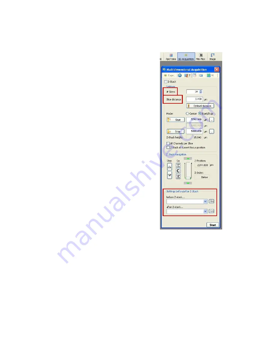
6.3 Z-Stack Settings 

Define the 

number of slices or the z-step size. 

By default, the 

software calculates the optimal z-step, or slice thickness, 
based on the axial resolution of the chosen objective and 
wavelength, and then determines the number of steps. You 
may override this by clicking on the button and entering a 
different step size or number of steps in the field. It is 
recommended to do an odd number of slices, usually, to 
ensure that the middle of your sample is not split between 
slices. You can also select the Optimal Distance icon below 
the slice distance and it will give you the mathematically 
determined option that will be on the verge of oversampling.  

The default of the Z-Stack is to go through each channel and 
image a Z-Stack. You can select the All Channels per slice 
option in the Settings section to allow all the channels to be 
imaged per slice before the movement to the next part of the 
Z-Stack.  Personal preference is the reason for why one 
option is selected over the other. Imaging one channel per Z-
Stack allows for the channels to have the specifications of the 
slice number and distance. However, the overlay of the 
channels might not be exactly the same such that the position 
of each slice might be different for each channel. This 
problem can be overcome with all channels per slice but this 
means that the acquisition will take longer.  

At the bottom of the window, you may or may not need to 
add settings for the microscope to do certain functions before 
the experiment begins. This could be as simple as turning on 
the fluorescence or activating only one filter position.   

Click Start to begin the acquisition sequence. After capturing 
a z-series, you will need to click on Z-Stack icon in the Z-Stack 
tab to remove Z-Stacks from acquiring in the future. 


Summary of Contents for AxioObserver

Page 1: ...Zeiss AxioObserver with ApoTome Quick Start User Guide AxioVision4 8 LSU Health Sciences Center Shreveport Research Core Facility RCF Microscopy...

Page 2: ...software Page 8 4 1 Experiment settings Page 9 4 2 Apotome Settings Page 10 4 3 Channel Creation Page 11 4 4 Setting Exposure Page 12 5 Acquiring and saving an experiment Page 13 5 1 Acquire Page 13...

Page 3: ...as the 10x objective in place This is a safety precaution If the 10x objective is not in place please clean the current objective and manually switch it to the 10x objective To manually switch objecti...

Page 4: ...supplies to press the button below the yellow sticker with the number 3 See image to the right This will turn on the TFT Display shown adjacently and please wait for this display to fully load before...

Page 5: ...Y direction of the stage The degree of which the stage will change will depend on which objective is in the light path The image to the right displays the Home screen and we will go over useful infor...

Page 6: ...if the Control icon on the sidebar is white and not blue An icon is selected if it is white and not selected icons will appear blue as shown to the right The Objectives displayed tell you which one i...

Page 7: ...bleed through 31 AF 568 EX 565 30 EM 620 60 for Cy 3 Texas Red 17 AF 488 EX 485 20 EM 540 25 for GFP FITC and prevents red emission bleed through 50 Cy 5 EX 640 30 EM 690 50 for Cy 5 and far red dyes...

Page 8: ...kets along the track The template will hold a variety of shapes If you need a multi well plate template please ask staff Start with DAPI to find and focus on your sample Be aware that fluorescence lig...

Page 9: ...ws a more detailed view of the options in the Workarea The Microscope selection allows you to adjust parts of the microscope similar to the options in the TFT display All options with a plus sign to t...

Page 10: ...the ApoTome from the microscope turn off its power supply first Labeled 4 which allows the grid to return to its original position then turn in back ON before you pull it part or all of the way out F...

Page 11: ...ull up the following window Next to the Experiment tab click on the blue circle icon to select different channels to acquire This icon represents different fluorescent and brightfield channels or mult...

Page 12: ...rkgroup DAPI selected in the During acquisition part of the Hardware Settings you will get an image of dye excitation similar to DAPI but will be labelled with TRITC Select the arrow the left of the G...

Page 13: ...exposed pixels Any pixel in red is over exposed and cannot be used in quantification data Also over exposure for long periods of time can damage the camera When you have adjusted the exposure time and...

Page 14: ...also export in other formats but it is recommended to export as a tiff later It is also advised that you save at regular intervals to protect your images from an unexpected software crash To export f...

Page 15: ...t the positions of the start and stop points to be past the region of interest This is to ensure that your entire region is in the Z Stack and that none of it is mathematically taken out Make sure tha...

Page 16: ...n select the All Channels per slice option in the Settings section to allow all the channels to be imaged per slice before the movement to the next part of the Z Stack Personal preference is the reaso...

Page 17: ...s However the cut view option overlays images on top of each other and causes over saturation of the stacked images To adjust the over saturated images do as follow 1 Turn off the channel coloring 2 s...

Page 18: ...oftware and log out of your user ID Also please write down the ending bulb time on the signup sheet when you sign out even if you are not turning it off If no one else is signed up to use the system f...

Page 19: ...es folder of the Programs folder After you have opened a blank Paint document click on Edit at the top of the window and select Paste from the drop down menu This should paste the screen shot and you...

Reviews: