background image

Install the hardware and connect all cables 

a. Installer the hardware 

1. Loosen the tamper-proof screws using supplied special hex wrench and remove the dome cover from the rugged 

dome. Be careful do not scratch the cover glass. 

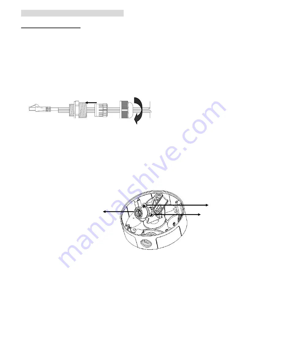
2. Disassemble the cable gland.   

3. Thread the network and I/O cable (power/audio/digital input and digital output) through thread-lock sealing nut, 

claw (using the claw to round all cable) and cable gland. To seal all cable in the claw part tightly in case of water 

leaking. 

4. Attach the cable gland to the conduit hole on the side or bottom of the rugged dome. Push the claw into the 

cable gland and tighten thread-lock sealing nut to secure the cables. 


5. Use the supplied blind plug to fill unused conduit hole. 

6. Use the drill template, drill four holes in the ceiling or wall. The conduit hole should face downwards if the 

camera is installed vertically. 

7. Install the rugged dome on the ceiling or wall using the supplied screws. Seal the holes with silicon sealant to 

prevent moisture from leaking in to the dome. 

8. Use the cable gland is optional. For vandal-proof requirement of the cables, use vandal-proof conduits instead.   

9. Turn the lens to the desired direction. Loosen the zoom puller and rotate the zoom and determine desired zoom 

position. Loosen focus puller and focus the image.   


10. After determining zoom and focus, lock the zoom puller and focus puller.       

11. Rotate the black protective shield inside the dome to match the camera’s position. 

12. Use soft cloth to clean dome cover glass to remove dust and finger prints and also use blower to remove dust 

from the lens. 

13. Remove the protective paper form the adhesive stripe on the side of rugged dome. Place the silica gel pack on 

the camera unit as suggestion. 

14. Cover dome and tighten the tamper-proof screws using the special hex wrench. 

Note: There might be of moisture problem which isn’t covered by warranty if dome is not installed by this 

instruction above.

Vari-focal Lens 

 Zoom puller 

Focus puller 

Summary of Contents for D6111

Page 1: ...Internet via Static IP Dynamic IP or both See P 13 Application of IP Camera See P 15 For more information please check the User Manual available in the Software CD or you can download the latest softw...

Page 2: ...Physical overview Dome cover Reset button Rugged dome RCA Wire clip Conduit hole plug Cable gland Thread lock sealing nut Cable gland Claw Note The size of Cable gland is M20 1 5 2...

Page 3: ...ged dome on the ceiling or wall using the supplied screws Seal the holes with silicon sealant to prevent moisture from leaking in to the dome 8 Use the cable gland is optional For vandal proof require...

Page 4: ...ged dome desired 2 Drill four holes in the wall or ceiling and insert plastic anchor nuts into them 3 Insert the supplied screws into the corresponding anchor nuts and secure them with screwdriver 4 C...

Page 5: ...tending 2 Loosen the two bolts to rotate bracket to the desired position 3 Thread all cable through cable gland 4 Route network cable and power cable then fixe those with wire clip 5 Attach cable glan...

Page 6: ...crewdriver d1 d Connect all cables b1 Power over Ethernet PoE 1 Using a standard RJ 45 network cable connect the IP Camera a PoE enabled Hub Switch Router on Camera to a normal Hub Switch Router to b2...

Page 7: ...se steps to install the firmware Select Intelligent IP Installer and follow the installation process to complete the installation Access the IP Camera using Intelligent IP Installer 1 Before using Int...

Page 8: ...om the list and click Link to IE 3 Enter your Username and Password to login to the IP Camera Default is admin admin 4 When accessing the IP Camera for the first time a yellow information bar appears...

Page 9: ...web browser Change light environment setting The default setting of lighting environment is Auto However you may also select 50 or 60 Hz upon the lighting environment of your country Go to Setting Bas...

Page 10: ...wser 2 Click Bonjour function and select the camera you wish to access 1 Select Safari icon 4 The monitor image will be displayed in your browser 3 Enter name and password to login to the IP camera De...

Page 11: ...tp IP mobile wml into your 2 5G web browser b1 Browser viewing For 2 5G mobile phone browser viewing type http IP mobile htm into your 2 5G web browser Windows Live Messenger Setting Live video of the...

Page 12: ...Option is enabled 10 Click on the small camera icon Then choose View a new contact s webcam Camera at home says 11 The IP Camera automatically accepts your invitation and its live video is displayed...

Page 13: ...ternet Connectivity of the IP Camera can be established through PPPoE Point to Point Protocol over the Ethernet by inputting the username and password from your Internet Service Provider ISP within th...

Page 14: ...UPnP Internet Gateway Device IGD turn on the UPnP function within the UPnP section Please go Setting Basic Network UPnP Note If you turn on the UPnP Port Forwarding function RTSP Real Time Streaming...

Page 15: ...Application of IP Camera 15...

Page 16: ...Memo...

Page 17: ...Memo...

Reviews: