background image

8

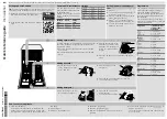
Three-phase version:
Power supply 400…415V 3N  

Figure 9

Open  the  power  supply  terminal  board  and  insert  the
jumpers provided as follows: one jumper between termi-
nals  2  and  4  and  another  between  terminals  4  and  6.
Using a suitable power supply cable (see technical data
table), connect the three phases to terminals 1, 3 and 5,
the neutral to terminal 4 and the earth wire to the termi-
nal 

.

Power supply 220...230V 3

Figure 10

Open  the  power  supply  terminal  board  and  insert  the
jumpers provided as follows: one jumper between termi-
nals  1  and  2,  one  between  terminals  3  and  4  and
another  between  terminals  5  and  6.  Using  a  suitable
power supply cable (see technical data table), connect
the three phases to terminals 1, 3 and 5 and the earth
wire to the terminal  

.

Power supply 220…230V 1N

Figure 11

Open  the  power  supply  terminal  board  and  insert  the
jumpers provided as follows: two jumpers between ter-
minals 1, 3, 5 and another two between terminals 2, 4
and 6. 
Using a suitable power supply cable (see technical data
table), connect the phase and neutral to terminals 5 and
6 respectively and the earth wire to the terminal 

.

Connections provided for energy control.

This appliance is designed for an external energy con-
sumption control.

Figure 12

Connect the energy peak controller across terminals 11
and 12.

Safety devices

An automatic reset thermoamperometric protective
device  incorporated  in  the  windings  of  the  electric
pump  cuts  off  the  electricity  supply  in  the  case  of
malfunctioning. 

In  the  event  of  water  mains  failure,  a  device  pre-
vents  water  in  the  boiler  from  returning  into  the
mains.

An overflow pipe, connected to the drainage outlet,
maintains the water in the tank at a constant level.

On  models  with  a  drain  pump,  a  supplementary
level control device activates if the main level con-
trol device is faulty.

Failure to comply with safety rules and regulations
relieves the manufacturer of all liability.

B3

DETERGENT/RINSE-AID DISPENSERS AND       
SETTINGS

If  the  appliance  is  connected  to  a  water  softener  or
osmotic  device,  contact  the  detergent  supplier  for  a
specific product.
Peristaltic dispensers (rinse-aid and detergent) require
periodic  maintenance.  The  internal  hose  of  the  rinse-
aid dispenser should undergo periodic maintenance 
(at least once or twice a year).

1. Dishwasher  with  incorporated  detergent  dis-

penser pump (Figure 13).

Pump “R” dispenses about 0.9 g/s of detergent. When
the appliance is filled with water for the first time in the
day,  it  dispenses  about  44  g  of  detergent  in  45  sec.,
thereby  providing  a  concentration  of  2  g/l.  Pump  “R”
dispenses about 6 g in 6 sec. at each cycle.
Dispenser  operating  time  may  be  changed,  following
the instructions given in the next paragraph.

L1

L2

L3

L1

L2

L3

CAUTION
A  normally  open  (n.o.)  contact  of  the
controller  must  be  connected  across
terminals  11  and  12.  When  this  contact
closes  the  boiler  heating  elements  are
disconnected.  Using  the  dishwasher  in
these conditions may increase the cycle
time.

11

12

!

Summary of Contents for NUC

Page 1: ...INSTALLATION DRIFT OG VEDLIGEHOLDELSE Side 59 FI ASTIANPESUKONE NUC EUC ZUCA ASENNUS K YTT JA HUOLTO Sivu 73 NO INNEBYGD OPPVASKMASKIN NUC EUC ZUCA MONTERING BRUK OG VEDLIKEHOLD Side 87 FR LAVE VAISSE...

Page 2: ......

Page 3: ...nt se r serve le droit de modifier sans pr avis les caract ristiques des appareils pr sent s dans cette publication Il Costruttore si riserva il diritto di modificare senza preavviso le caratteristich...

Page 4: ...ART Seite 21 B1 WASSERANSCHLUSS Seite 21 B2 ELEKTROANSCHLUSS Seite 21 B3 VORBEREITUNGEN UND DOSIERER F R SP LMITTEL KLARSP LMITTEL Seite 23 B4 REGULIERUNG DER DOSIERER Seite 24 B5 WARTUNG Seite 25 C A...

Page 5: ...inem Hub wagen oder Gabelstapler diese m ssen breiter sein als die H lfte der Abmessungen des Produktes A2 ENTFERNUNG DER VERPACKUNG Abb 1 Unter Verwendung von Arbeitshandschuhen die Ver packung entfe...

Page 6: ...0 300 2 3 Wassertemperatur Zulauf C 50 50 50 50 50 Wasserh rte Zufuhr fH dH 14 8 max 14 8 max 14 8 max 14 8 max 14 8 max Wasserverbrauch pro Klar sp lgang l 3 3 3 3 3 3 3 3 Fassungsverm gen Boiler l 5...

Page 7: ...u rohr Innendurchmesser 40 mm int 18 mm I Stromversorgung S Eingang Sp lmittelschl uche Q Potentialausgleichsschraube Nur bei Modell mit Fallrohr Nur bei Modell mit Ablaufpumpe C A I I Q 30 162 255 20...

Page 8: ...r vorzuschalten Bei dem Modell mit Fallrohr Das Ablaufrohr C Abb 4 unter Verwendung eines Siphons an die Abflussleitung anschlie en oder das Rohr ber ein im Fu boden eingelassenes Siphonsieb positioni...

Page 9: ...g ffnen und die mit gelieferten berbr ckungen wie folgt einsetzen zwei berbr ckungen zwischen den Klemmen Nr 1 3 und 5 und zwei weitere zwischen den Klemmen Nr 2 4 und 6 Mit einem geeigneten Stromvers...

Page 10: ...n Klarsp lmittelbeh lter einsetzen nur bei den Ausf hrungen ohne eingebau ten Klarsp lmittelbeh lter 3 Geschirrsp ler mit eingebauter Membranklar sp lerpumpe Abb 13 Die Pumpe T ist bei den Ger ten mit...

Page 11: ...NCE PERSON Page 7 B1 WATER CONNECTION Page 7 B2 ELECTRICAL CONNECTION Page 7 B3 DETERGENT RINSE AID DISPENSERS AND SETTINGS Page 8 B4 SETTING THE DISPENSERS Page 10 B5 MAINTENANCE Page 11 C INSTRUCTIO...

Page 12: ...HANDLING Use suitable means to move the appliance a lift truck or fork pallet trucks the forks should reach more than halfway beneath the appliance A2 UNPACKING Figure 1 Wear protective gloves to unp...

Page 13: ...mp C 50 50 50 50 50 Water supply hardness fH dH 14 8 max 14 8 max 14 8 max 14 8 max 14 8 max Rinse cycle water consumption l 3 3 3 3 3 3 3 3 Boiler capacity l 5 8 5 8 5 8 5 8 5 8 Tank capacity l 33 33...

Page 14: ...gs C Outlet pipe i 40 mm i 18mm I Power supply S Pipe inlet for detergents Q Unipotential screw Only for model with free fall drainage Only for model with drain pump C A I I Q 30 162 255 202 62 46 508...

Page 15: ...rap or place the outlet pipe over an S trap set into the floor On the model with drain pump position the outlet pipe at a height anywhere between 750 and 1000 mm from the floor Check that about 4 litr...

Page 16: ...rporated in the windings of the electric pump cuts off the electricity supply in the case of malfunctioning In the event of water mains failure a device pre vents water in the boiler from returning in...

Page 17: ...e sensor and liquid detergent injector should be installed without prejudicing the watertightness of the appliance Electrical connections for automatic detergent and rinse aid dispensers Single phase...

Reviews: