background image

rdq-6 instruction manual

z-systems audio laboratories

17

So far, we’ve only discussed bell-shaped parametric filters.  We will now turn our attention to
shelving filters.  Whereas bell-shaped filters are used to emphasize or de-emphasize a range of
frequencies in a bell-shaped region about a center frequency, a shelving filter is used to
emphasize or de-emphasize all of the frequencies above or below a desired corner frequency.
A shelving filter is characterized by a pair of parameters: the corner frequency and the gain.
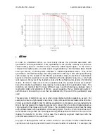
For example, consider the shelving filters shown in Figure 18.  These curves correspond to a
low-shelving filter with a corner frequency of 500 Hz and gains of -2 dB, -6 dB, and -12 dB,
respectively.  Ideally, a low-shelving filter would be flat until the corner frequency and drop to
a value specified by the gain for all frequencies below the corner frequency.  In practice, these
filters have a finite slope, as shown in Figure 18.

The corner frequency is tough to “eyeball” from these plots.  Loosely speaking, it is the
frequency at which the magnitude response deviates by 3 dB from the 0-dB reference  (which
only makes sense for filters that have shelves lower than -3 dB).  For example, the bottom
curve in Figure 18 is down by 3 dB at roughly 500 Hz.  Below 500 Hz, the curve continues to
slope downward, approaching flatness at a level of -12 dB.  We have not shown a low shelving
filter with boost instead of cut, but this too is permissible.

F

IGURE 

18

A high-shelving filter is similar to a low-shelving filter.  The only difference is that frequencies
above the corner frequency are boost or cut.  Figure 19 shows a family of curves for a high
shelving filter with a corner frequency of 5 kHz.

Summary of Contents for rdq-6

Page 1: ...tems audio laboratories products 30 contact information 31 introduction Congratulations on your purchase of the rdq 6 digital reference equalizer The rdq 6 is the result of many years of research and development in digital audio technology and when used properly it will create a home theater experience you may not have thought possible from your system The purpose of this document is to give you a...

Page 2: ...ack The rdq 6 can also be used in a mode we call super two channel mode S2 mode When in S2 mode the rdq 6 can apply all of its equalization bands to a two channel source yielding 18 bands of parametric equalization per channel This allows the rdq 6 to function much like our rdp 1 and rdq 1 processors but with more power and flexibility For example twelve of the equalization bands could be used for...

Page 3: ... and off 5 System menu button Allows the user to access the input selection load and save functions output wordwidth controls and the stereo dual mono link controls 6 Menu buttons These multi function buttons work in conjunction with the display In the normal operating mode shown above pressing one of these buttons will bring the filter shown directly above it into focus When in any other mode the...

Page 4: ...channel is chosen the display will show all of the filter parameters for that channel 10 Infra red remote sensor rear panel layout The only audio connectors visible on the rdq 6 s rear panel are three sets of XLR AES EBU digital inputs and outputs and three sets of RCA S PDIF digital inputs and outputs The main power switch and the AC mains connector are also located on the rear panel This is show...

Page 5: ...IF input on an RCA connector 1 AES EBU output on an XLR connector 1 S PDIF output on an RCA connector Regardless of which input is selected both outputs are active simultaneously To select which input is used by the rdq 6 press the system button and select the INPUT submenu The display will appear as shown in Figure 4 To change the active input simply rotate the knob below the input selection disp...

Page 6: ... in S2 mode the L R TTC label will also be shown and the link status for this board can be changed as well Pressing the button underneath BACK will take you to the system menu and pressing the button underneath EXIT will return you to the normal operating mode output wordwidth dither selection For a more thorough discussion of dither please refer to Appendix A The rdq 6 allows you to control the d...

Page 7: ... each of the three processor cards Pressing the button underneath BACK will take you to the system menu and pressing the button underneath EXIT will take you to the normal operating mode volume control The analog volume control is a potential source for noise and coloration Nonetheless most of us are willing to live with these problems in light of the other problems that life without a volume cont...

Page 8: ...o full scale The same could happen while comparing presets It is for this reason that the volume setting is unaffected by the load and save functions and bypass whatever the value of volume is dialed in will remain in place during preset loads or during bypass individual volume offsets In a home theater system it is not at all uncommon that the speakers may have markedly different sensitivities fr...

Page 9: ...ch channel is being displayed turn the center knob until the channel you would like to see is shown If either the front or surround processor cards are in stereo linked mode you will not see the individual left and right channels for these banks they will be displayed as a stereo pair The same is true for the TTC pair if it is linked mode If you would like to apply tone control separately to the l...

Page 10: ...oes not affect the volume This is because we want it to be impossible for the user to accidentally bring the volume to full scale Because the bypass mode cancels the dither hitting bypass when the volume is set to anything other than 0 dB can result in very subtle sonic differences due to truncation depending on the program material and the volume Therefore doing a level matched comparison between...

Page 11: ... You may have a negative impression of digital domain tone control indeed there have been many poor implementations in the past Rest assured we re confident you ll find TTC to be free from any non beneficial coloration and to be the finest tone control you ve ever heard TTC is a direct implementation of the digital equalization algorithm used in our line of professional disc mastering equalizers I...

Page 12: ... for bell filter 1 the knob below the gain display controls the amount of boost cut the knob below the frequency display controls the center frequency and the knob below the slope display controls the slope The audio signal is affected in real time when any of the parameters are changed Pressing the button underneath EXIT will take you back to the normal operating mode and the display for the filt...

Page 13: ...allow you to compare presets against one another This section describes how to use the rdq 6 s preset facility save preset FIGURE 13 How to do it Suppose you have dialed in the rdq 6 s controls to a setting you find pleasing you are happy with the bell filters the shelf filters the input and the dither for all six channels You can save this setting so it can be recalled at a later time or so that ...

Page 14: ... B buttons It is important to note that a and b are nothing more than placekeepers They can be set to any values even the same values The only reason we have provided the b preset is for simple comparison between two settings For example suppose you wish to compare preset 1 with preset 49 this would be difficult without the a b controls You should make note of two particular preset numbers Loading...

Page 15: ... is defined as the ratio of the filter s center frequency fc to filter s bandwidth BW Formally we have the relation Q f BW c We can see from this equation that for a given center frequency as we make the bandwidth smaller the value of Q increases The same discussion holds valid for bell filters in boost mode rather than in cut mode Rather than describing the bell filters bandwidths in terms of Q w...

Page 16: ...er frequency and gain constant Figure 16 shows the effect of holding the slope and gain constant while moving the center frequency Figure 16 shows a family of frequency response curves for a slope equal to 05 a gain of 6 dB and center frequencies of 100 Hz 1 kHz and 10 kHz respectively Notice that the filters have identical shapes when viewed on a logarithmic frequency axis FIGURE 16 Finally Figur...

Page 17: ...uld be flat until the corner frequency and drop to a value specified by the gain for all frequencies below the corner frequency In practice these filters have a finite slope as shown in Figure 18 The corner frequency is tough to eyeball from these plots Loosely speaking it is the frequency at which the magnitude response deviates by 3 dB from the 0 dB reference which only makes sense for filters t...

Page 18: ...istortion can manifest itself in many different ways including harshness edginess loss of reverberant detail and alteration of timbre Loosely speaking then a digital audio system s performance is bounded by a level that is established by the size of the quantization step used This same type of distortion can occur when doing digital to digital operations as well For example to ensure a high qualit...

Page 19: ...haracteristics of the system It may seem paradoxical that the key to eliminating digital distortion is through the addition of noise but this is indeed the case Dither will increase the system s overall noise level but the resulting noise floor is much more like an analog noise floor Interestingly in a properly dithered system signal details far smaller than the smallest quantization step can be h...

Page 20: ...issing sound much like analog tape noise This hissing however is much more benign than the harmonic distortion induced by truncation Upon listening the signal in Figure 21 is not recognizable as a sine wave The signal in Figure 22 however sounds like a sine wave in a low level hissing background The same can be said for other low level signals not just laboratory produced sine wave test signals Th...

Page 21: ...t DACs were the norm even the smallest amount of attenuation could cause the data to underflow the DAC Today with 20 bit DACs in common use up to 24 dB of attenuation can be made without DAC underflow And as the dither discussion illustrates resolution well beyond the LSB is possible we typically claim a number of 12 dB beyond the LSB This extension beyond the LSB in conjunction with the 20 bit DA...

Page 22: ...lue displayed by the rdq 6 slope 01 corresponds to a Q equal to Q0 Subsequent values of slope give multiples of Q0 Specifically we have slope 01 corresponds to Q0 slope 02 corresponds to 2Q0 slope 03 corresponds to 2 27Q0 slope 04 corresponds to 3 25Q0 slope 05 corresponds to 5Q0 slope 06 corresponds to 6 25Q0 slope 07 corresponds to 7 5Q0 slope 08 corresponds to 10Q0 slope 09 corresponds to 12 5Q...

Page 23: ... as a result of finite precision can recirculate through the filter There are many different ways to compute the difference equation given by Equation 1 For example there are different ways to arrange the order of summation and products or there are alternative formulations to realize the same output y k as a rearrangement of different intermediate sums and products Whatever the realization the or...

Page 24: ...hat is optimal in the above sense There are several solutions to this problem and they differ slightly as a function of the optimality criteria they use The solution we have derived has a number of useful properties Most significantly our architecture realizes the absolute minimum possible roundoff noise power and sensitivity to coefficient quantization Equally interesting our architecture always ...

Page 25: ...panel is facing you Slide the lid towards you and away from the chassis of the unit Locate the ribbon cable that extends from the back panel s DB 9 connector to the right edge of the display circuit board You will notice that it is plugged into the bottom connector on the edge of the display circuit board This is the RS 422 connector To set the unit to receive RS 232 input plug this ribbon cable t...

Page 26: ...ume value specified by word2 to all of the outputs The value of word2 corresponds to gains of 95 0 dB 00h to 12 0 dB 9Ah For a complete listing of these values refer to the table below word2 word2 GAIN GAIN 00h 95 0 dB 01h 90 0 dB 02h 85 0 dB 03h 80 0 dB 04h 75 0 dB 05h 66 0 dB 06h 62 0 dB 07h 59 0 dB 08h 56 0 dB 09h 53 0 dB 0Ah 50 0 dB word2 word2 GAIN GAIN 0Bh 48 0 dB 0Ch 46 0 dB 0Dh 44 0 dB 0Eh...

Page 27: ...q 6 The following table shows the values for word2 for each combination of inputs Word2 Word2 L R Front L R Front Input Input L R Surround L R Surround Input Input Center Sub Center Sub Input Input 00h XLR XLR XLR 01h RCA XLR XLR 02h XLR RCA XLR 03h RCA RCA XLR 04h XLR XLR RCA 05h RCA XLR RCA 06h XLR RCA RCA 07h RCA RCA RCA ...

Page 28: ...ter frequency resolution 1 6 th octave ISO from 28 Hz to 18 kHz Filter gain cut from 95 dB to 12 0 dB Filter bandwidths 12 steps from Q 0 4 to Q 8 0 nominal Shelf filter slopes 6 dB octave Dither types 20 bit and 16 bit proprietary floating point techniques Digital filter architecture proprietary minimum roundoff noise structure Dynamic range better than 144 dB THD N better than 135 dB Processor t...

Page 29: ...is includes all surround sound processors CD transports DACs etc Make sure there are no cables attached to the rdq 6 s inputs or outputs Next follow the instructions below to reach and replace the fuses 1 Turn the power off and remove the power cord from both the wall and from the rdq 6 2 Remove the four screws securing the bottom of the lid to the chassis and then remove the four screws securing ...

Page 30: ...io Laboratories product returned under this warranty and found by the factory to be operating in accordance with its stated specifications In the event that your Z Systems Audio Laboratories product requires warranty service take the unit along with its packing material and proof of purchase to any authorized Z Systems Audio Laboratories dealer The dealer will take care of the repair Direct shipme...

Page 31: ...tative between the hours of 9 00 AM and 6 00 PM EST Monday through Friday at 352 371 0990 If calling to report a problem with your unit please have the serial number and the name of the place of purchase handy If you should have to return the unit to the factory for service please call to receive a Return Material Authorization number If it is deemed necessary that your unit be sent in for repair ...

Reviews: