rdq-6 instruction manual
z-systems audio laboratories
15
appendix A: equalization and dither
•
equalization
The TTC consists of two types of filters: bells and shelves. These filters derive their names from
their frequency-domain shapes. The bell filter is characterized by three parameters: the
center frequency, the amount of cut (or boost), and the bandwidth. Bell filters are typically
used for applications such as resonance control, room mode control, and narrow-band noise
reduction, to name a few. The bell filter has a typical gain of 0 dB (unity gain) with a
maximum cut of -g dB occurring at the center frequency. The bandwidth, expressed in Hertz,
is defined as the width of the filter at its -3 dB points. It is typical to express the bandwidth of a
bell filter in terms of its quality factor, Q. The Q parameter is defined as the ratio of the filter's
center frequency, fc, to filter's bandwidth, BW. Formally, we have the relation
Q
f
BW
c
=
We can see from this equation that for a given center frequency, as we make the bandwidth
smaller, the value of Q increases. The same discussion holds valid for bell filters in boost mode
rather than in cut mode. Rather than describing the bell filters’ bandwidths in terms of Q, we
have chosen to display on the front panel a parameter we call “slope.” Slope is related to Q in
a straightforward fashion, as detailed in Appendix B.
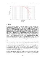
F
IGURE
15
For most users, it will suffice to understand how the slope parameter works in a qualitative
sense. Consider the widest filter shown in Figure 15, which has a center frequency of 1000 Hz
and a cut of –6 dB. As we vary the slope while keeping the center frequency and gain
constant, the bandwidth of the filter changes. As the slope increases, the bandwidth
decreases (that is, the filter gets narrower). On the rdq-6, the slope varies from 1 to 12, with a


