background image

Y Z   S y s t e m s   M i l t o n   R o y   •   2 0 1   I v y l a n d   R o a d   •   I v y l a n d ,   PA  •   U S A  •   1 8 9 7 4   •   P :   2 8 1 . 3 6 2 . 6 5 0 0   •   w w w. y z s y s t e m s . c o m

Page 37 

NJEX 610G / 610F  ver.11-2023

Appendix A:  Illustrations

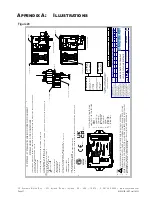
Figure 20

Z-100 CONTROLLER

FLOW SWITCH (OPTIONAL)

SOLENOID

LVO SYSTEM

xxxx

YYYY

DYNAPAK SYSTEM

Z-100 CONTROLLER

SOLENOID

CYCLONE SYSTEM

Z-100 CONTROLLER

SOLENOID

SYSTEM LEVEL CONNECTIONS 

MADE AT Z-100 CONTROLLER:

RELAY +
1.

RELAY -
2.

ANALOG IN
3.

COMMON
4.

FLOW SWITCH
5.

EXT. POWER
6.

COMMON
7.

NBS IN
8.

COUNT IN
9.

SOLENOID -
10.

S
11.

THIS WIRING CONTROL DOCUMENT COVERS THE FOLLOWING YZ SYSTEMS PR

ODUCT LINES USING THE Z-100 CONTROLLER:

LVO LOW VOLUME ODORIZER 610G OR 610F DYNAPAK 20X0, 30X0 CYCLONE MLS-4400

THE SYSTEMS LISTED ABOVE HOLD THE FOLLOWING APPROVALS:

CLASS I, DIVISION 1, GROUPS C-D, T4 PROVIDES INTRINSICALLY SAFE OUTPUTS FOR CLASS I, DIVISION 1, GR

OUPS C-D AND CLASS I, ZONE 0, GROUP IIB

CLASS I, ZONE 0, AEx ia [ia] IIB T4 Ga Ex ia [ia] IIB T4 Ga II 1(1)G Ex ia [ia] IIB T4 Ga -20

C ≤ Ta ≤ +60

C

IP54

ETL23CA104230006X IECEx ETL 23.0013X ETL23ATEX0290X ITS23UKEX0707X

Conforms to UL STD 60079-0, 60079-11, 61010-1 Certified to CSA STD C22.2 NO. 60079-0, 60079-11, 61010-1-12

INTRINSICALLY SAFE INTRINSEQUEMENT SUR

SPECIAL CONDITIONS OF USE

ALL SYSTEMS ARE INTENDED FOR FIXED INSTALLATION

1.

POTENTIAL ELECTROSTATIC CHARGING HAZARD.  EQUIPMENT SHALL BE CL

EANED WITH A DAMP CLOTH.

2.

YZ SYSTEMS - SYSTEM LEVEL WIRING CONTROL DOCUMENT

SYSTEMS USING Z-100 CONTROLLER

NOTES:


EX

 SCHEDULE DRAWING - DO NOT MODIFY WITHOUT AGENCY APPROVAL.

1.

  ASSEMBLIES SHOWN DO NOT COVER ALL CONFIGURATIONS FOR EACH PRO

DUCT LINE.  

2.

REFER TO THE MODEL CODE ABOVE FOR ALL MODELS COVERED UNDER THIS

 DOCUMENT.

SEE WIRING CONTROL DOCUMENT 2E-0042 FOR ALL WIRING AND APPROVAL

3.

INFORMATION ON THE Z-100 CONTROLLER.

3193094

Z-100 CONTROLLER

External I.S. Supply Ui: 28VDC Ii: 178mA Pi: 1.245W

Internal Battery Pack Ui: 15.6VDC Ii: 299.18mA Pi: 1.054W

SOLENOID

50mA @ 12VDC 

NOMINAL

FLOW SWITCH

(LVO 610F 

MODELS ONLY)

SEE WIRING CONTROL DOCUMENT  2E-0042 FOR ALL WIRING DETAILS 

FOR CONTROLLER

DATE

ECN

DESCRIPTION

Drawn - 

Dessiné / Visa

Checked - Vérifié / Visa

REV

REVISION HISTORY

7/6/2023

29593

DRAFT RELEASE

TRA

SS

00

12

H

G

F

E

D

C

B

A

J

K

L

M

N

P

Q

R

A

B

C

D

E

F

G

H

J

K

L

M

N

P

11

10

9

8

7

6

5

4

3

2

1

13

14

15

16

17

18

19

20

21

22

23

24

1

2

3

4

5

6

7

8

9

10

11

12

13

14

15

16

17

18

19

20

23

21

24

22

T

R


REV

2000 - 4000

2[.079]

1000 - 2000

1.2[.047]

400 - 1000

0.8[.031]

120 - 400

0.5[.020]

30 - 120

0.3[.012]

6 - 30

0.2[.008]

GENERAL  TOLERANCE

ISO 2768

FIRST ANGLE PROJECTION

DO NOT SCALE DRAWING

DESSIN SANS ECHELLE

0.2

[0.079]

0.6

[0.024]

0.4

[0.016]

TOLERANCES mm[ INCHES]

125

RMS

Ra

FINISH

SHEET - FEUILLE 

GEOMETRIC TOLERANCES

TOLÉRANCES GÉOMÉTRIQUES

LINEAR DIMENSIONS - DIMENSIONS LINÉAIRES mm[INCHES]

DESCRIPTION

A0

1

/

1

<3.2 

DRAWING NUMBER - PLAN N°

.5 - 6

FORMAT TAILLE


0.1[.004]


2E-0054

WIRING CONTROL DOCUMENT

00

LVO, DP, CYCLONE SYSTEMS

PROPRIETARY NOTICE

THIS DRAWING CONTAINS  CONFIDENTIAL AND TRADE SECRET  INFORMATION. IS THE PROPERTY OF  INGERSOLL-RAND CO., AND IS GIVEN  TO THE RECEIVER IN CONFIDENCE. THE  RECEIVER BY RECEPTION AND  RETENTION OF THE DRAWING  ACCEPTS THE DRAWING IN  CONFIDENCE AND AGREES THAT,  EXCEPT AS AUTHORIZED IN WRITING BY  INGERSOLL-RAND CO., IT WILL (1) NOT  USE THE DRAWING OR ANY COPY  THEREOF OR THE CONFIDENTIAL OR  TRADE SECRET INFORMATION THEREIN;  (2) NOT COPY THE DRAWING; (3) NOT  DISCLOSE TO OTHERS EITHER THE  DRAWING OR THE CONFIDENTIAL OR  TRADE SECRET INFORMATION THEREIN;  AND (4) UPON COMPLETION OF THE  NEED TO RETAIN THE DRAWING, OR  UPON DEMAND, RETURN THE  DRAWING, ALL COPIES THEREOF, AND  ALL MATERIAL COPIED THEREFROM.

WARNING: THE EXPORT OR REEXPORT OF THIS DRAWING OR A PRODUCT PR

ODUCED BY THIS DRAWING IS SUBJECT TO U.S. EXPORT 

ADMINISTRATION REGULATIONS AND OTHER APPLICABLE GOVERNMENT REST

RICTIONS OR REGULATIONS

Summary of Contents for NJEX LVO 610G

Page 1: ...NJEX LVO 610G NJEX LVO 610F N A T U R A L G A S O D O R I Z A T I O N S Y S T E M...

Page 2: ......

Page 3: ...NJEX LVO 610G 610F Instruction Operating Manual Version 11 2023...

Page 4: ...m Connections 7 Section 3 Filling the Bulk Odorant Tank 8 Filling the Tank for the First Time 8 Refilling the Bulk Odorant Tank 9 Section 4 System Control Electronics 10 Overview 10 Section 5 Programm...

Page 5: ...tion 7 Mechanical System 24 Overview 24 NJEX LVO Gas Filter 25 Model 6000 pump 26 Flow Switch 27 Section 8 System Maintenance 28 Preventative Maintenance Schedule 28 Recommended Spare Parts List 28 Se...

Page 6: ...ns a hyperlink to the referenced item Items that require action for example the press ing of a key for programming the controller will feature the action item in sentence case Bold Text followed in no...

Page 7: ...ed an external relay contact from external device can be connected to the Inhibit NBS input to inhibit and restart pump operation Proportional to Time Timer Mode Operation In Timer mode the pump is ac...

Page 8: ...System Accessories Odorant Injection Probe includes a 316 stainless steel probe and isolation valve for lo cation at the pipeline When ordering please specify pipeline connection required or Odorant I...

Page 9: ...nd the odorant discharge manifold IP54 rated E NJEX LVO Gas Filter Installed between the actuation gas regulator and the actuation gas manifold this filter provides a 25 micron coalescent filtration t...

Page 10: ...89 13 8 bar 30 psi 2 07 bar 200 500 psi 13 89 34 5 bar 40 psi 2 76 bar 500 900 psi 34 5 62 1 bar 50 psi 3 45 bar 900 1400 psi 62 1 96 5 bar 60 psi 4 14 bar Z 100 Analog or Pulse Input By Customer V13...

Page 11: ...ection of 2 pipe in a vertical configuration at the location where the NJEX LVO 610G NJEX LVO 610F is to be installed Using the mounting clamps provided with the NJEX LVO 610G NJEX LVO 610F system att...

Page 12: ...ring performance To prolong the service of seals and o rings adequate heat should be provided to maintain an operating environment above 32 F 0 C 2 Connect the pump discharge valve fitting to the pipe...

Page 13: ...elow V10 is observed then partially open V11 to allow ambient air from the tank to begin flowing out Allow this process to continue until all ambient air from the tank is purged and only inert gas or...

Page 14: ...ng Figure 6 Closed V10 V11 V13 3 Connect a line from V11 to a flare or vapor recovery device and open V11 4 Attach odorant supply to V10 open V10 and begin transferring odorant to the bulk tank CAUTIO...

Page 15: ...accordance with the Wiring Control Document see Figure 20 The Z 100 rated for use in Class I Division 1 Groups C D and IECEx ATEX Zone 1 hazardous locations WARNING Electrostatic Discharge Hazard Wipe...

Page 16: ...would like to move To open sub menus enter parameters etc you will use the navigation like a push button and push by pressing in the center of the switch When viewing a screen note if there is an arro...

Page 17: ...the navigation switch left for approximately 1 second to start or stop system Bottom left has timer countdown to next pump stroke in counter mode a of accumulated pulses is shown Totalizer From the H...

Page 18: ...ndividually Note the arrow underneath the digit that is currently being edited Press the left or right arrow to change which digit is updated To change the value press the navigation switch up or down...

Page 19: ...ble an indicates the currently selected mode Once a mode has been selected press the left key to exit back to the Mode Menu Timer Mode In timer mode the controller actuates the 6000B pump at a set tim...

Page 20: ...to 1 000V and the Flow Zero Screen will show CALIBRATED indicating that a user calibration value is being used If the flow signal is too far out of range a RANGE ERROR message will be shown and there...

Page 21: ...puts and report system status Flow No Signal The Flow No Signal setting deter mines the percentage of max gas flow the 610G F system will assume as the current pipeline flow when a valid flow signal i...

Page 22: ...seasonal changes the BACK PRESSURE setting should be updated accordingly Density The ODORANT DENSITY setting is used in the cal culations for estimating the mass odorant injected and odorization rate...

Page 23: ...ll have a single line dash next to the alarm Press the navigation switch left to exit the sub menu Battery Low The Battery Low alarm is an indication the battery voltage is low and should be replaced...

Page 24: ...ume odorizing when power is restored system is OFF when power is lost it will remain OFF when power is restored To enable open the Resume on Power Loss sub menu Press navigation switch up or down and...

Page 25: ...Output activity Pump Test and Date Time changes MM100 When ready to download the Z 100 logged data remove the rubber plug located in the opening on the bottom of the Z 100 enclosure and insert the MM...

Page 26: ...nput setting If the REMOTE INHIBIT input setting is ON or NBS upon entry the INHIBIT TEST screen will show the INHIBIT test type INHIBIT ON or INHIBIT NBS with NOTTESTING status Press enter on the nav...

Page 27: ...d the LED will flash GREEN If the battery voltage is found to be low during the test the LED will flash RED A fully charged new battery pack will measure approximately 14 4V if measured with a DMM or...

Page 28: ...b 3 Desired injection rate lb MMCF or mg m c 4 Average flow rate MCF hr or m hr d 5 Timer setting a English a x b x 15 8503 c x d a Metric a x b x 60000 c x d Example 1 Example 2 English Gas Flow Metr...

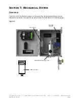
Page 29: ...0F ver 11 2023 Section 7 Mechanical System Overview The 610G 610F mechanical system is composed of the mechanical electrical enclosure Individual components of the system are shown below and described...

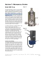
Page 30: ...d 30 60 psi 2 1 4 1 bar per Table 1 Page 5 actuation gas supply provided by the system operator By conditioning the incoming actuation gas a clean pneumatic supply will be provided to the solenoid val...

Page 31: ...rtridge design in key areas that may require maintenance They are the inlet check valve the discharge check valve and the plunger bushing seal assembly The cartridge design provides easier maintenance...

Page 32: ...e factory but may need to be adjusted for the installation site To adjust the flow switch loosen the set screw C and move the reed switch contact B up or down and tighten the set screw On the home scr...

Page 33: ...he odorant and the odorant bulk storage tank and the pump stroke frequency All of these issues must be considered when establishing a preventative maintenance schedule Recommended Maintenance Schedule...

Page 34: ...ssistance is available 24 hours a day 7 days a week 365 days a year via the telephone numbers listed above SAFETY NOTES Always use extreme care when performing maintenance on an odorization system Che...

Page 35: ...be tested with the battery test option under the test menu Navigate to the battery test menu and press enter on the navigation switch While in the battery test menu press the navigation switch in to t...

Page 36: ...d remove the actuation gas line at the top of the pump and test the pump stroke again As the Test key is pressed there should be a burst of gas at the open actuation supply connection If the gas is re...

Page 37: ...rrect as needed 2 Check that the pump is operating as ex pected If the pump is not stroking see the pump troubleshooting section 3 If the pump is functioning as expected go to the Z 100 Controller ter...

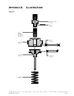
Page 38: ...PA U S A 1 8 9 7 4 P 2 8 1 3 6 2 6 5 0 0 w w w y z s y s t e m s c o m Page 33 NJEX 610G 610F ver 11 2023 Appendix A Illustrations NJEX LVO Model 6000B pump Assembled Actuation Gas Actuation Gas Odor...

Page 39: ...o m Page 34 NJEX 610G 610F ver 11 2023 Appendix A Illustrations O Ring P N A5 1013 Actuation Fitting Assembly P N A1 0216 O Ring P N A5 1127 Actuation Seal P N A6 0076 Actuation Spring P N C3 0036 Pi...

Page 40: ...Ring O Ring O Ring P N A5 1117 P N A5 1118 P N B0 1030 Bottom Cartridge P N A6 0091 Secondary Seal P N A6 0090 Seal Support P N A6 0089 Primary Seal P N B0 1033 Stop Bushing CV Inlet Wafer O Ring P N...

Page 41: ...endix A Illustrations Figure 19 Gas Filter Label PN D5 0074 O Ring 334 Viton PN A5 1334 Coalescing Filter Element1 PN C4 0133 Filter Retainer Washer PN C4 0102 Filter Bowl PN C4 0131 In Gas Filter Cap...

Page 42: ...3193094 Z 100 CONTROLLER External I S Supply Ui 28VDC Ii 178mA Pi 1 245W Internal Battery Pack Ui 15 6VDC Ii 299 18mA Pi 1 054W SOLENOID 50mA 12VDC NOMINAL FLOW SWITCH LVO 610F MODELS ONLY SEE WIRING...

Page 43: ...hnical data the export of which is or may be restricted by the Export Administration Act and the Export Administration Regulations EAR 15 C F R parts 730 774 Diversion contrary to U S law is prohibite...

Page 44: ...oy 201 Ivyland Road Ivyland Pennsylvania USA 18974 P 281 362 6500 www yzsystems com NJEX 610G 610F ver 11 2023 201 Ivyland Road Ivyland PA 18974 P 281 362 6500 F 281 362 6513 techsupport yzsystems com...

Reviews: