Imagined by You
™
www.tiohome.com
AZSS1 Installation Guide
8
For tabletop installation, skip to Wiring Connections below.
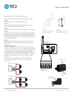
STEP 1
Identify a place to install the AZSS1 in the wall.
STEP 2
Cut out a rough opening into the wall and install a single
gang low voltage ring and tighten it down.
STEP 3
Pull the power and other audio wires to the new audio location.
STEP 4
Locate the in-wall mounting bracket that came with the AZSS1.
Align the in-wall mounting bracket so that it lines up properly
with the front panel of the AZSS1. Locate the small screws from
the installation package. Secure the in-wall mounting bracket
to the front of the AZSS1.
STEP 5
Make all wiring connections per the instructions below and
then insert the AZSS1 with bracket into the single gang low-
voltage ring.
WIRING CONNECTIONS
Locate the speaker connector block that came in a clear pack
of accessories with your AZSS1. Loosen the four screws before
attempting to connect the speaker wire. With your speaker wire
ends trimmed back 1/4” inch (.64 cm) insert each speaker wire
and tighten down each screw. Note the polarity: positive (+)
speaker wire on the outside terminal and negative (–) speaker
wire on the inside terminal. See diagrams below for wiring
speakers.
Note: Make sure locking tabs on mating side of Speaker
Connector locks over the top of the receiving connector on
the AZSS1.
Installation - Standard In-wall
STEP 1
In-wall mounting bracket
with small screws
STEP 2
Single gang low-voltage
ring with large screws
Removable
Speaker Connector
+ L – – R +
+ L –
– R +
Insert Speaker
Wires
Loosen Screws
Lock Tabs Over
Connector
Parallel Speaker Wire Diagram
+
–
+
–
+
–
+
–
Right
Left
4 Ohm
Load
8 Ohms
8 Ohms
8 Ohms
8 Ohms
+
–
+
–
Speaker Wire Diagram
+
–
+
–
Right
Left
4 Ohm
Load
4 Ohms
4 Ohms
+
–
+
–
WIRING
CONNECTIONS


