


835959-UIM-D-0814
4
Johnson Controls Unitary Products
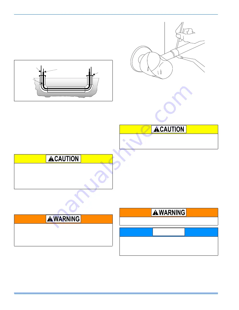
6. Use PVC piping as a conduit for all underground installations as
shown in Figure 3. Keep buried lines as short as possible to mini-
mize the build up of liquid refrigerant in the vapor line during long
periods of shutdown.
7. Pack fiberglass insulation and a sealing material such as permagum
around refrigerant lines where they penetrate a wall to reduce vibra-
tion and to retain some flexibility.
8. See Application Data Part Number 247077 for additional piping infor-
mation.
PRECAUTIONS DURING BRAZING OF LINES
All outdoor unit and evaporator coil connections are copper-to-copper
and should be brazed with a phosphorous-copper alloy material such
as Silfos-5 or equivalent. DO NOT use soft solder. The outdoor units
have reusable service valves on both the liquid and vapor connections.
The total system refrigerant charge is retained within the outdoor unit
during shipping and installation. The reusable service valves are pro-
vided to evacuate and charge per this instruction.
Serious service problems can be avoided by taking adequate precau-
tions to assure an internally clean and dry system.
PRECAUTIONS DURING BRAZING SERVICE VALVE
Precautions should be taken to prevent heat damage to service valve
by wrapping a wet rag around it as shown in Figure 4. Also, all painted
surfaces, insulation, and the plastic base should be protected during
brazing. After brazing, joint should be cooled with wet rag.
Valve can be opened by removing the plunger cap and fully inserting a
hex wrench into the stem and backing out counter-clockwise until valve
stem just touches the chamfered retaining wall.
Connect the refrigerant lines using the following procedure:
1. Remove the cap and Schrader core from both the liquid and vapor
valve service ports at the outdoor unit. Connect low pressure nitro-
gen to the liquid line service port.
2. Braze the liquid line to the liquid valve at the outdoor unit. Be sure to
wrap the valve body with a wet rag. Allow the nitrogen to continue
flowing. Refer to the Tabular Data Sheet for proper liquid line sizing.
3. Go to SECTION IV, and accomplish the TXV Installation procedure.
4. Braze the liquid line to the evaporator liquid connection. Ensure that
nitrogen is flowing through the evaporator coil to prevent oxidation
during brazing procedure.
5. Remove the split rubber grommet from the vapor connection at the
indoor coil. Braze the vapor line to the evaporator vapor connection.
After the connection has cooled, place the rubber grommet back into
the mounting position. Refer to the Tabular Data Sheet for proper
vapor line sizing.
6. Protect the vapor valve with a wet rag, and braze the vapor line con-
nection to the outdoor unit. Ensure that the nitrogen flow is exiting
the system from the vapor service port connection. After this connec-
tion has cooled, remove the nitrogen source from the liquid fitting
service port.
7. Replace the Schrader core in the liquid and vapor valves.
8. Leak test and repair leaks in all refrigerant piping connections includ-
ing the service port flare caps. DO NOT OVERTIGHTEN caps.
Torque caps between 40 and 60 inch - lbs. maximum.
9. Evacuate the vapor line, the evaporator, and the liquid line to 500
microns or less in accordance with the EVACUTATION procedures.
FIGURE 3:
Underground Installation
Dry nitrogen should always be supplied through the tubing while it is
being brazed, because the temperature required is high enough to
cause oxidation of the copper unless an inert atmosphere is provided.
The flow of dry nitrogen should continue until the joint has cooled.
Always use a pressure regulator and safety valve to insure that only
low pressure dry nitrogen is introduced into the tubing. Only a small
flow is necessary to displace air and prevent oxidation.
This is not a backseating valve. The service access port has a valve
core. Opening or closing valve does not close service access port.
If the valve stem is backed out past the chamfered retaining wall, the
O-ring can be damaged causing leakage or system pressure could
force the valve stem out of the valve body possibly causing personal
injury.
TO INDOOR COIL
TO OUTDOOR UNIT
LIQUID LINE
CAP
PVC
CONDUIT
INSULATED
VAPOR LINE
A0152-001
FIGURE 4:
Heat Protection
Do not install any coil in a furnace which is to be operated during the
heating season without attaching the refrigerant lines to the coil. The
coil is under 30 to 35 psig inert gas pressure which must be released
to prevent excessive pressure build-up and possible coil damage.
Never attempt to repair any brazed connections while the system is
under pressure. Personal injury could result.
Refrigeration piping and indoor coil can be pressurized to 250 psig
with dry nitrogen and leak tested with a bubble type leak detector.
Then release the nitrogen charge.
Do not use the system refrigerant from the outdoor unit to purge or
leak test the system.
A0153-001
NOTICE


