background image

5121495-UIM-E-0716

Johnson Controls Unitary Products

17

Operation

The defrost mode is equivalent to the cooling mode except that the out-
door fan motor is de-energized. The control shall do the following to ini-
tiate a defrost cycle.

De-energize the outdoor fan.

Energize the reversing valve.

Energize the auxiliary heat output through the Wout terminal.

Begin the maximum defrost cycle length timer.

If the call for heating (Y) is removed from the control during the defrost
cycle, it will terminate the defrost cycle and de-energize the compres-
sor. The control will also stop the defrost cycle length timer but not reset
it. When the control receives another call for heating, it will restart the
defrost cycle and the timer at the point at which the call for heating was
removed. This will happen only if the coil sensor temperature conditions
allow defrost to occur.

Defrost Curves

The control uses a set of defrost curve parameters that are selected
using the defrost curve selection jumper. The location of the defrost
curve selection jumper is shown on the Tabular Data sheet for each
heat pump model.

Defrost Curve Selection

The second page of the tabular data sheet indicates the proper jumper
setting for the specific heat pump model.

The control only reads the jumper input when the Y and W thermostat
inputs are de-energized. If a jumper position is changed while either of
these inputs is energized, the control will not act upon the jumper
changes until the thermostat calls are de-energized or power (24 VAC)
to the control is cycled.

Defrost Cycle Initiation

The control will allow the heat pump to operate in the heating mode until
the combination of outdoor ambient and outdoor coil temperatures indi-
cate that a defrost cycle is necessary. 

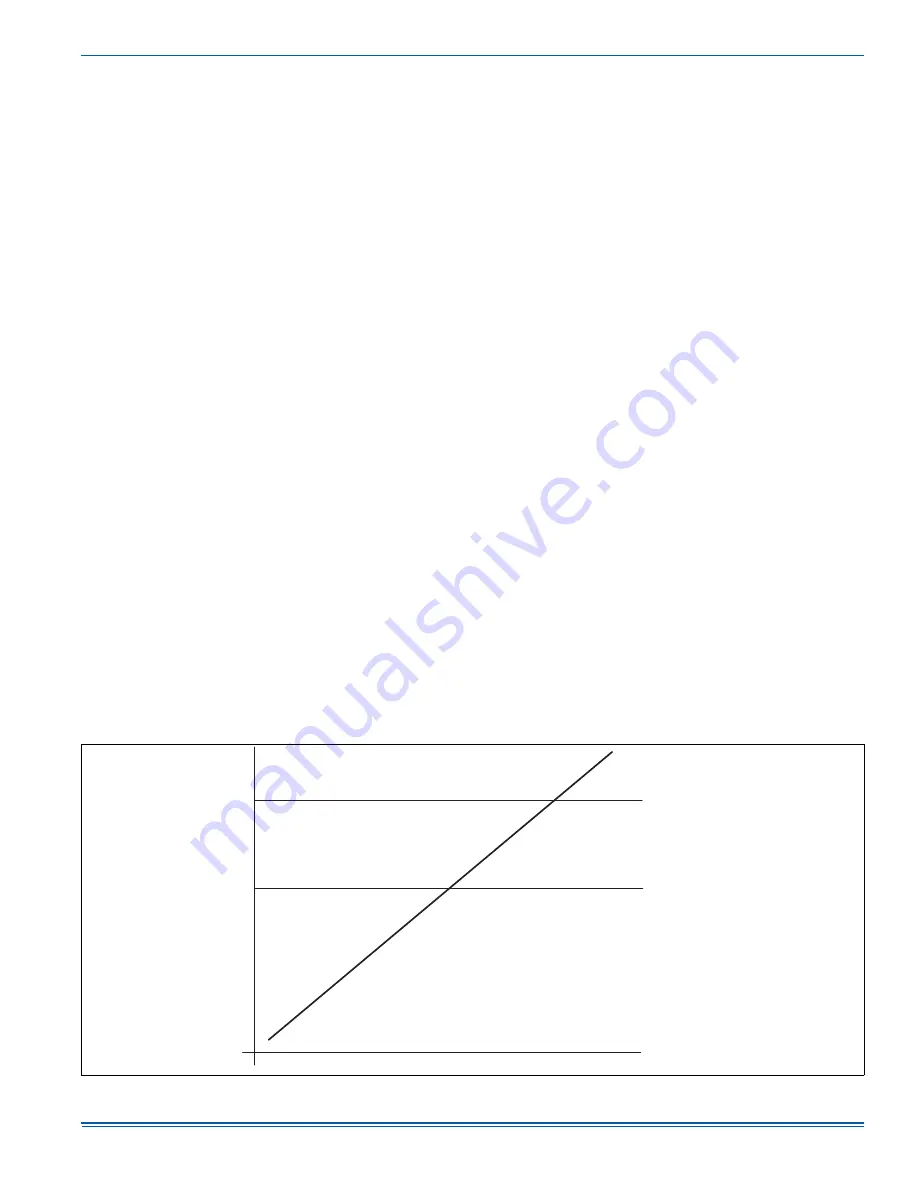
The control will initiate a defrost cycle when the coil temperature is
below the initiate point for the measured ambient temperature (See Fig-
ure 14) continuously for 4-1/2 minutes. This delay eliminates unneces-
sary defrost cycles caused by refrigeration surges such as those that
occur at the start of a heating cycle.

The control will initiate a defrost cycle every 6 hours (accumulated com-
pressor run time) to recirculate refrigerant lubricants. This forced
defrost timer will be reset and restarted following the completion or ter-
mination of a defrost cycle.

The control shall initiate a defrost cycle when the Defrost Inhibit Time
Limit has elapsed if the previous defrost cycle was terminated based on
the Maximum Defrost Cycle Time. This shall occur regardless of the liq-
uid line (coil) temperature reading. The coil does not have to be cold for
the unit to be forced into defrost. Once the defrost cycle begins the con-
trol shall follow the normal defrost cycle routine.

The control will also initiate a defrost cycle when the TEST terminals
are shorted. This feature allows an installer or service technician to start
a defrost cycle immediately as required. When the TEST terminals are
shorted for more than 5 seconds with a Y input energized and the pres-
sure switch input is closed, the ASCD will be bypassed, the reversing
valve will be energized, the ODF will be de-energized and the compres-
sor and the Wout terminal to auxiliary heat will be energized.

When the TEST inputs are used to force a defrost cycle, the control will
ignore the state of the coil temperature and outdoor ambient tempera-
ture inputs. The coil does not have to be cold and the outdoor tempera-
ture does not have to be within a certain range for the heat pump to be
forced into a defrost cycle. After the TEST input jumper is removed, the
defrost mode will be terminated as normal. The defrost cycle length
timer will not be started until the TEST input is removed. If the TEST ter-
minals remain shorted, the control will keep the unit in defrost mode.

Defrost Inhibition

The control will not initiate a defrost cycle if the liquid line temperature is
above 40°F unless the defrost cycle is forced using the TEST input, or
the previous defrost exited on maximum time (12 minutes).

The control will also prevent a defrost cycle from being initiated too
soon after the initiation of the previous defrost cycle. When power is
applied to the control and after the completion or termination of each
defrost cycle, the control will start a 40-minute timer. When this timer
expires, the control will allow another defrost cycle when needed. The
timer is based on accumulated compressor run time.

Defrost Termination

The control will terminate the defrost cycle immediately after the liquid
line temperature reaches the terminate temperature or after 12 minutes
of defrost operation. See Figure 14.

The control will do the following to terminate a defrost cycle:

Energize the outdoor fan.

De-energize the reversing valve.

De-energize the auxiliary heat output through the Wout terminal.

Reset and restart the 40-minute defrost inhibit timer.

 FIGURE 14: 

Defrost Operation Curves

RE

G

ION C

TER

M

INATE CURVE

IN

H

I

B

IT CURVE

INITIA

TE

CUR

VE

RE

G

ION A

RE

G

ION 

B

RE

G

ION D

RE

G

ION E

A

MB

IENT TE

M

PERATURE

LIQUID LINE 

(

COIL

)

TE

M

PERA

TURE

D

e

f

rost


prevente

d f

rom


starting

N

o


ca

ll f

or

 d

e

f

rost

T

ime

 D

e

f

rost


(6


hour)


prevente

d

N

o


ca

ll f

or

 D

e

f

rost

T

ime

 D

e

f

rost


(6


hour)


a

ll

owe

d

C

a

ll f

or

 D

e

f

rost

D

e

f

rost

T

erminate

d

A

0144-001

Summary of Contents for YHE Series

Page 1: ...1 YHE60 Heat Charging Charts 12 TEST Input Functionality with Y 15 TEST Input Functionality without Y 15 Status Code Display 16 Status 16 SECTION I GENERAL The outdoor units are designed to be connected to a matching indoor coil with sweat connect lines Sweat connect units are factory charged with refrigerant for a nominal sized matching indoor coil plus 15 feet of field supplied lines Matching in...

Page 2: ...There is an Optional Cold Weather Charging accessory kit to prevent the outdoor unit from taking in cold air below 55 F The kit part number can be found in the list of accessory kits on the UPGNET web site Provide adequate structural support for the unit ADD ON REPLACEMENT RETROFIT When this unit is being used as a replacement for an R 410A unit it is required that the outdoor unit indoor coil and...

Page 3: ...cess and serviceability as well as the possible sound and vibration transmission into the structure These applications are best served by a properly engineered solution UNIT PLACEMENT 1 Provide a base in the pre determined location 2 Remove the shipping carton and inspect for possible damage 3 Ensure that compressor tie down bolts remain tightened 4 Position the unit on the base provided LIQUID LI...

Page 4: ...n internally clean and dry system PRECAUTIONS DURING BRAZING SERVICE VALVE Precautions should be taken to prevent heat damage to service valve by wrapping a wet rag around it as shown in Figure 4 Also protect all painted surfaces insulation and plastic base during brazing After braz ing cool joint with wet rag Valve can be opened by removing the service valve cap and fully insert ing a hex wrench ...

Page 5: ...discharged loosen and remove the Schrader core 3 Place a backup wrench on distributor loosen and remove brass distributor nut Retain brass nut for use on liquid line Keep Teflon washer in place and discard clear disk 4 Install the thermal expansion valve to the distributor assembly with supplied fittings Ensure Teflon washer is seated in distributor Hand tighten and turn an additional 1 4 turn to ...

Page 6: ...rge added accordingly MEASURE INDOOR AIR FLOW To determine rated air flow for a specific match consult the technical lit erature at www upgnet com When attempting to match this air flow select the lowest possible speed tap measure the actual flow and adjust as necessary To measure actual air flow it is not an acceptable method to just check the jumper pin setting tables and is to assume 0 5 water ...

Page 7: ...brated pressure gauge is not available place a R 410A virgin refrigerant container in a conditioned space long enough to come to tempera ture equilibrium with the surroundings Then measure the tem perature of the air and the pressure of the refrigerant and compare it to the following table Before measuring the pressures use the method above to check the air flow and then consult the table and matc...

Page 8: ...2 378 424 307 353 399 301 349 396 290 336 382 270 314 357 261 303 346 Suction Pressure PSIG 147 120 104 86 63 56 YHE TH4 RHP14L18 FC MC PC24 FC MC PC30 CFM Ambient Temperature F 60 47 40 30 17 10 Indoor Temperature F 60 70 80 60 70 80 60 70 80 60 70 80 60 70 80 60 70 80 450 Liquid Pressure PSIG 382 428 474 352 395 437 337 385 433 319 364 410 275 325 376 276 319 362 600 Liquid Pressure PSIG 346 391...

Page 9: ... 350 396 294 340 385 282 327 373 268 306 345 262 301 339 Suction Pressure PSIG 130 106 94 78 59 52 YHE TH4 THE RHP14L30 CF CM CU36 CF CM CU42 AP AVC30 AP AE AVC36 FC MC PC32 FC MC PC35 AHE30 AHV30 CFM Ambient Temperature F 60 47 40 30 17 10 Indoor Temperature F 60 70 80 60 70 80 60 70 80 60 70 80 60 70 80 60 70 80 800 Liquid Pressure PSIG 366 413 460 343 390 437 306 366 426 315 360 405 291 331 370...

Page 10: ...7 256 296 337 241 281 322 231 273 316 Suction Pressure PSIG 136 109 96 80 60 52 YHE TH4 RHP14L35 FC MC PC48 AHE AHV42 CFM Ambient Temperature F 60 47 40 30 17 10 Indoor Temperature F 60 70 80 60 70 80 60 70 80 60 70 80 60 70 80 60 70 80 1000 Liquid Pressure PSIG 321 365 408 301 344 386 290 335 379 274 318 361 255 296 337 246 288 329 1200 Liquid Pressure PSIG 301 342 383 283 313 367 275 308 362 261...

Page 11: ...essure PSIG 321 347 374 277 320 363 271 316 360 259 299 340 243 284 325 234 276 319 Suction Pressure PSIG 123 101 89 72 50 44 YHE THE TH4 RHP14L42 FC MC PC60 AHE48 AHV48 CFM Ambient Temperature F 60 47 40 30 17 10 Indoor Temperature F 60 70 80 60 70 80 60 70 80 60 70 80 60 70 80 60 70 80 1100 Liquid Pressure PSIG 357 386 415 306 349 392 295 340 385 279 323 367 259 301 342 250 292 334 1300 Liquid P...

Page 12: ...0 363 267 311 356 250 289 328 237 280 323 225 256 288 Suction Pressure PSIG 128 105 93 76 57 50 TABLE 9 YHE48 Heat Charging Charts Continued TABLE 10 YHE60 Heat Charging Charts YHE THE TH4 RHP14L60 CF CM CU64 AE60D AVC60D CFM Ambient Temperature F 60 47 40 30 17 10 Indoor Temperature F 60 70 80 60 70 80 60 70 80 60 70 80 60 70 80 60 70 80 1615 Liquid Pressure PSIG 340 385 430 315 345 404 302 333 3...

Page 13: ... CONNECTIONS POWER WIRING 1 Install the proper size weatherproof disconnect switch outdoors and within sight of the unit 2 Remove the screws at the top and sides of the corner cover Slide the control box cover down and remove from unit 3 Run power wiring from the disconnect switch to the unit 4 Route wires from disconnect through power wiring exit provided and into the unit control box as shown in...

Page 14: ...ommended that a mini mum air flow of 325 cfm ton be supplied at all times To see connection diagrams of all UPG equipment the Low Voltage System Wiring document is available online at www upgnet com in the Product Catalog Section INDOOR CUBIC FEET PER MINUTE CFM SELEC TION BOARD SETTINGS Typical Refer to the indoor unit Installation Manual instructions for the air han dler or furnace interface wit...

Page 15: ...owing table summarizes the behavior of the control when the two TEST pins are connected More detailed descriptions of the various functions are included in other sec tions of this document TABLE 11 TEST Input Functionality with Y Duration of connection seconds Control behavior with thermostat signals present 2 No response 2 5 Bypass ASCD Reduce timer to zero immediately If Y1 is present and high p...

Page 16: ... arrangement of the refrigeration circuit within the coil The control may initiate a defrost cycle even when the coil is not completely cov ered with frost This is normal operation The control regulates the defrost operation of the heat pump based on accumulated compressor run time outdoor coil temperature and out door ambient temperature The control will cause the heat pump unit to operate in the...

Page 17: ...ccur regardless of the liq uid line coil temperature reading The coil does not have to be cold for the unit to be forced into defrost Once the defrost cycle begins the con trol shall follow the normal defrost cycle routine The control will also initiate a defrost cycle when the TEST terminals are shorted This feature allows an installer or service technician to start a defrost cycle immediately as...

Page 18: ...sh code The control will reset the soft lockout condition when any of the follow ing occur after removal of the fault condition 1 Power is cycled to the R or Y inputs of the control This will cause the soft lockout condition to be reset when the thermostat is satis fied or when the thermostat is set to SYSTEM OFF and back to HEAT or COOL mode 2 The TEST terminals are shorted for more than two seco...

Page 19: ...CTRICAL SHOCK OPEN REMOTE DISCONNECT SO ELECTRICAL SUPPLY TO HEAT PUMP IS SHUT OFF COMPONENTS SHOWN IN DASH LINES ARE OPTIONAL DUAL CAPACITOR SHOWN SEPARATE CAPACITORS MAY BE USED ON ACTUAL UNIT WIRING MUST CONFORM TO NATIONAL AND LOCAL CODES IF ANY OF THE ORIGINAL WIRE SUPPLIED WITH THIS UNIT MUST BE REPLACED IT MUST BE REPLACED WITH 105 C THERMOPLASTIC OR ITS EQUIVALENT WHERE POWER SUPPLY HAS ON...

Page 20: ...IBLE PERSONAL INJURY TO PREVENT ELECTRICAL SHOCK OPEN REMOTE DISCONNECT SO ELECTRICAL SUPPLY TO HEAT PUMP IS SHUT OFF COMPONENTS SHOWN IN DASH LINES ARE OPTIONAL WIRING MUST CONFORM TO NATIONAL AND LOCAL CODES IF ANY OF THE ORIGINAL WIRE SUPPLIED WITH THIS UNIT MUST BE REPLACED IT MUST BE REPLACED WITH 105 C THERMOPLASTIC OR ITS EQUIVALENT 1 2 3 LEGEND AS AMBIENT SENSOR CAP CAPACITOR CC CONTACTOR ...

Page 21: ... TO PREVENT ELECTRICAL SHOCK OPEN REMOTE DISCONNECT SO ELECTRICAL SUPPLY TO HEAT PUMP IS SHUT OFF COMPONENTS SHOWN IN DASH LINES ARE OPTIONAL WIRING MUST CONFORM TO NATIONAL AND LOCAL CODES IF ANY OF THE ORIGINAL WIRE SUPPLIED WITH THIS UNIT MUST BE REPLACED IT MUST BE REPLACED WITH 105 C THERMOPLASTIC OR ITS EQUIVALENT 1 2 3 LEGEND AS AMBIENT SENSOR CAP CAPACITOR CC CONTACTOR COIL CCH CRANKCASE H...

Page 22: ...5121495 UIM E 0716 22 Johnson Controls Unitary Products NOTES ...

Page 23: ...Data Venting if applicable Electrical Line Voltage Outdoor Unit Model Outdoor Unit Serial Filter Thermostat Accessories Filter Location s Connections Per Installation Instructions and Local Codes Gas piping is connected if applicable Supply plenum and return ducts are connected and sealed Filter Size Vent system is connected if applicable Thermostat wiring complete Heat anticipator is set to the r...

Page 24: ... ie ON OFF or the appropriate Value for the fields that apply to the defrost control board installed Run Time Time and Temperature board only 30 60 or 90 minutes Bonnet Sensor Present HEAT Refrigerant Charge and Metering Device TXV Fixed Orifice R 410A Oz 45s Elbows TXV Orifice Size Liquid Line Temp Subcooling Superheat High Side Pressure Low Side Pressure Suction Line Temp Additional Lineset Leng...

Reviews: