


JOHNSON CONTROLS
27
SECTION 2 – SYSTEM OPERATING PROCEDURES
FORM 160.69-O2
ISSUE DATE: 9/30/2020
2
NEED FOR MAINTENANCE OR SERVICE
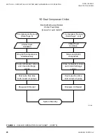
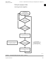
If the system is malfunctioning in any manner or the
unit is stopped by one of the safety controls, consult the
“Operation Analysis Chart”, (
),
of this instruction. After consulting this chart, if you
are unable to make the proper repairs or adjustments to
start the compressor or the particular trouble continues
to hinder the performance of the unit, please call the
nearest YORK District Office. Failure to report con-
stant troubles could damage the unit and increase the
cost of repairs.
STOPPING THE SYSTEM
The Optiview™ Control Center can be programmed to
start and stop automatically (maximum, once each day)
whenever desired.
Refer to Form 160.69-O1
. To stop
the chiller, proceed as follows:
1. Push the
COMPRESSOR STOP/RESET
switch. The compressor will stop automatically.
The oil pump will continue to run for coastdown
period. The oil pump will then stop automatically.
2. Stop the chilled water pump (if not wired into
the Microcomputer Control Center, in which
case it will shut off automatically simultaneously
with the oil pump.) (The actual water pump con-
tact operation is dependent upon the position of
Microboard jumper J54.)
3. Open the switch to the cooling tower fan motors,
if used.
4. The compressor sump oil heater is energized
when the unit is stopped.
PROLONGED SHUTDOWN
If the chiller is to be shut down for an extended pe-
riod of time (for example, over the winter season), the
following paragraphs outline the procedure to be fol-
lowed.
1. Test all system joints for refrigerant leaks
with a leak detector. If any leaks are found,
they should be repaired before allowing the
system to stand for a long period of time.
During long idle periods, the tightness of the
system should be checked periodically.
2. If freezing temperatures are encountered
while the system is idle, carefully drain the
cooling water from the cooling tower, con-
denser, condenser pump, and the chilled wa-
ter system-chilled water pump and coils.
Open the drains on the evaporator and condenser
liquid heads to assure complete drainage. (If a
Variable Speed Drive, drain its water cooling sys-
tem. If Solid State Starter. drain water from starter
cooling loop.)
3. On the
SETUP
Screen, disable the clock. This
conserves the battery.
4. Open the main disconnect switches to the com-
pressor motor, condenser water pump and the
chilled water pump. Open the 115 volt circuit to
the Control Center.
Summary of Contents for YD A
Page 8: ...JOHNSON CONTROLS 8 FORM 160 69 O2 ISSUE DATE 9 30 2020 THIS PAGE INTENTIONALLY LEFT BLANK...
Page 22: ...JOHNSON CONTROLS 22 FORM 160 69 O2 ISSUE DATE 9 30 2020 THIS PAGE INTENTIONALLY LEFT BLANK...
Page 28: ...JOHNSON CONTROLS 28 FORM 160 69 O2 ISSUE DATE 9 30 2020 THIS PAGE INTENTIONALLY LEFT BLANK...
Page 34: ...JOHNSON CONTROLS 34 FORM 160 69 O2 ISSUE DATE 9 30 2020 THIS PAGE INTENTIONALLY LEFT BLANK...
Page 48: ...JOHNSON CONTROLS 48 FORM 160 69 O2 ISSUE DATE 9 30 2020 THIS PAGE INTENTIONALLY LEFT BLANK...