


JOHNSON CONTROLS
11
SECTION 1 – DESCRIPTION OF SYSTEM AND FUNDAMENTALS OF OPERATION
FORM 160.69-O2
ISSUE DATE: 9/30/2020
1
Level Control Setpoint. This ramp allows the level to
go from the present level to the Level Control Setpoint
over a period programmed as the
Ramp Up Time
Setpoint
. After the Ramp Up time has elapsed, the
level is controlled to the Level Control Setpoint.
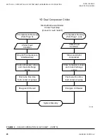
After the Chiller Pulldown Period ends, if the Lag
compressor has not been brought on line during the
Chiller Pulldown Period, the Chiller Steady State
Period begins. During this period, the Pre-rotation
Vanes are modulated to maintain the Leaving Chilled
Liquid Temperature Setpoint. In order to determine if
the Lead compressor is meeting the load demand dur-
ing this period, the Leaving Chilled Liquid Tempera-
ture minus the Leaving Chilled Liquid Temperature
Setpoint (Temperature Differential) is monitored. If
the Temperature Differential exceeds the Maximum
Delta T Setpoint (1.0 ºF to 5.0 ºF; default 1.0) for a
period equal to the Maximum Delta T Time Setpoint (1
to 20 minutes; default 5) and the Chiller Current Limit
Setpoint is above 50%, the Lag compressor is brought
on line.
With only one compressor running, the compressor
Variable Geometry Diffuser is modulated according to
the stall and surge activity.
When bringing the Lag Compressor on line, it enters
the Prelube period. If a high head condition exists, the
Lead compressor’s Pre-rotation vanes are driven closed
as described in “Lag Start with High Head” below. The
Refrigerant Level Control Lag Start mode is initiated as
described below under “Condenser Refrigerant Level
Control Lag Start”. During the Lag Prelube, all normal
Prelube functions are performed except the Oil Pres-
sure Transducer Offset calibration is not performed.
The offset calculation from the Lead compressor start
is used. The Prelube time is fixed at 50 seconds. At the
completion of the Prelube, the Lag compressor motor
is started and after a 50 second delay, the Lag com-
pressor Discharge Valve is opened (If it doesn’t fully
open within 40 seconds as indicated by the Discharge
Valve Limit Switch, a Safety shutdown is performed
on both compressors and “Discharge #X – Valve Not
Opened” is displayed). After the Discharge Valve has
fully opened, the Lag compressor Pre- rotation Vanes
are modulated to follow Lead motor current.
Meanwhile, the Lead compressor Pre-rotation Vanes
have been modulated to maintain the Leaving Chilled
Liquid Temperature setpoint (unless “Lag Start with
High Head” was performed). When the Lag motor
current is 5% of the Lead motor current, the
run time of the compressors are evaluated to deter-
mine which should be the Lead compressor (The one
with the least amount of run time is identified as the
Lead compressor) and if a “Lag Start with High Head”
was performed, the Lead Pre-rotation vanes are now
allowed to open and control per the Leaving Chilled
Liquid Temperature Setpoint. Two minutes after the
Lag compressor Discharge Valve has opened, the Con-
denser Refrigerant Control ramp-up period begins as
Described below under “Condenser Refrigerant Level
Control – Lag Start”. While both compressors are run-
ning, the Variable Geometry Diffusers are modulated
according to the stall activity and Pre-rotation Vanes
position. There is no VGD response to surge activity.
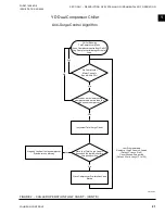
When both compressors have been brought online,
they will be run for at least 30 minutes (unless the anti-
recycle feature has been disabled, a fault is detected or
a Local or Remote stop is applied). After the 30 minute
waiting period, a Soft Shutdown (as described below)
will be performed on the Lag compressor if the Lead
compressor motor current goes below the
Low Load
Setpoint
(20% to 60%; default 45%) for a period equal
to the
Low Load Time Setpoint
(1 to 20 minutes; de-
fault 5).
Lag Compressor Start with High Head
(Software version C.MLM.11.02.xxx and later or
C.OPT.11.02.300 and later)
When operating at high head conditions, surges can
occur while going from one to two compressor opera-
tion. A high head condition is detected by measuring
the Delta P/P [(Condenser pressure – Evaporator pres-
sure) / Evaporator pressure] and comparing it to the
HIGH HEAD DP/P LIMIT Setpoint. By closing the
Lead compressor’s pre-rotation vanes during a Lag
compressor start when a high head condition is pres-
ent, surge conditions can be minimized.
With the Lead compressor running and it is determined
the Lag compressor is required to run, the Delta P/P
is measured. If it is > the HIGH HEAD DP/P LIMIT
Setpoint, a close signal is applied to the Lead compres-
sor’s pre-rotation vanes coincident with the start of the
Lag Compressor’s Pre-lube. They will be allowed to
open when all the following conditions are met: the
lag compressor is running, the Lag Discharge Valve is
open, the difference between the Lead and Lag motor
currents is < 5%.
Summary of Contents for YD A
Page 8: ...JOHNSON CONTROLS 8 FORM 160 69 O2 ISSUE DATE 9 30 2020 THIS PAGE INTENTIONALLY LEFT BLANK...
Page 22: ...JOHNSON CONTROLS 22 FORM 160 69 O2 ISSUE DATE 9 30 2020 THIS PAGE INTENTIONALLY LEFT BLANK...
Page 28: ...JOHNSON CONTROLS 28 FORM 160 69 O2 ISSUE DATE 9 30 2020 THIS PAGE INTENTIONALLY LEFT BLANK...
Page 34: ...JOHNSON CONTROLS 34 FORM 160 69 O2 ISSUE DATE 9 30 2020 THIS PAGE INTENTIONALLY LEFT BLANK...
Page 48: ...JOHNSON CONTROLS 48 FORM 160 69 O2 ISSUE DATE 9 30 2020 THIS PAGE INTENTIONALLY LEFT BLANK...