SECTION 2 – PRODUCT DESCRIPTION
FORM 201.26-NM1
ISSUE DATE: 1/19/2018
JOHNSON CONTROLS
17
2
Programmable setpoints
• Chilled liquid temperature setpoint and range
• Remote reset temperature range
• Set daily schedule/holiday for start/stop
• Manual override for servicing
• LOW liquid temperature cutout
• LOW suction pressure cutout
• High discharge pressure cutout
• Anti-recycle timer (compressor start cycle time)
• Anti-coincident timer (delay compressor starts)
Displayed Data
• Return and leaving liquid temperature
• Low leaving liquid temperature cutout setting
• Metric or Imperial data
• Discharge and suction pressure cutout settings
• System discharge and suction pressure
• Anti-recycle timer status for each compressor
• Anti-coincident system start timer condition
• Compressor run status
• No cooling load condition
• Day, date and time
• Daily start/stop times
• Holiday status
• Automatic or manual system lead/lag control
•
Lead system definition
• Compressor starts and operating hours (each com-
pressor)
• Run permissive status
• Number of compressors running
• Liquid solenoid valve status
• Load and unload timer status
• Water pump status
System Safeties
Cause individual compressors to perform auto shut
down and require manual reset in the event of three
trips in a 90-minute time period:
• High discharge pressure
• Low suction pressure
• High pressure switches
• Motor protector
Unit Safeties
Unit Safeties are automatic reset and cause all com-
pressors to shut down:
• Low leaving chilled liquid temperature
• Under voltage
•
Loss of liquid flow (through flow switch)
• Low battery
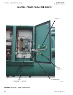
Power and Control Panels
All power and controls are contained in an IP32 cabi-
net with hinged, latched and gasket sealed outer doors.
POWER PANEL
The power panel includes:
• A factory mounted Non-fused Disconnect Switch
with external, lockable handle to enable connec-
tion of the unit power supply. The disconnect
switch can be used to isolate the power for servic-
ing.
• Factory mounted compressor contactors and man-
ual motor starters to provide overload and short
circuit protection.
• Factory mounted control transformer to convert
the unit supply voltage to 115V, 1-phase, 60Hz for
the control system.
Summary of Contents for YCWL0056SE
Page 4: ...FORM 201 26 NM1 ISSUE DATE 1 19 2018 JOHNSON CONTROLS 4 THIS PAGE INTENTIONALLY LEFT BLANK...
Page 30: ...FORM 201 26 NM1 ISSUE DATE 1 19 2018 JOHNSON CONTROLS 30 THIS PAGE INTENTIONALLY LEFT BLANK...
Page 146: ...FORM 201 26 NM1 ISSUE DATE 1 19 2018 JOHNSON CONTROLS 146 THIS PAGE INTENTIONALLY LEFT BLANK...
Page 154: ...FORM 201 26 NM1 ISSUE DATE 1 19 2018 JOHNSON CONTROLS 154 THIS PAGE INTENTIONALLY LEFT BLANK...
Page 168: ...FORM 201 26 NM1 ISSUE DATE 1 19 2018 JOHNSON CONTROLS 168 THIS PAGE INTENTIONALLY LEFT BLANK...
Page 186: ...FORM 201 26 NM1 ISSUE DATE 1 19 2018 JOHNSON CONTROLS 186 NOTES...


