SECTION 7 – UNIT CONTROLS
FORM 201.26-NM1
ISSUE DATE: 1/19/2018
JOHNSON CONTROLS
129
7
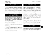
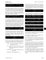
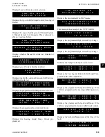
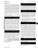
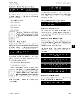
F A N C O N T R O L O N
P R E S S U R E = X X X P S I G
Displays the programmed Fan On Pressure.
F A N D I F F E R E N T I A L O F F
P R E S S U R E = P S I G
This message does not apply to a YCWL chiller.
S Y S 1 T R I P V O L T S
= X . X V O L T S
Displays the programmed High Current Trip Voltage.
S Y S 2 T R I P V O L T S
= X . X V O L T S
Displays the programmed High Current Trip Voltage.
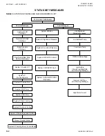
Y
O
R
K H Y D
R
O
K I T P U
M
P S = X
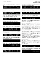
Indicates the Pump Control option is selected.
L C H L T = X X X . X ° F
R C H L T = X X X . X ° F
Displays the Leaving and Return chilled Liquid Tem-
perature at the time of the fault.
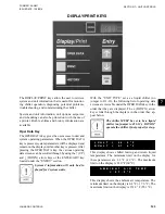
S E T P O I N T = X X X . X ° F
R A N G E = + / - ° F
Displays the programmed Setpoint and Range, if the
chiller is programmed for leaving chilled liquid con-
trol.
S E T P O I N T = X X X . X ° F
R A N G E = + X X . X ° F
Displays the programmed Setpoint and Range, if the
chiller is programmed for return chilled liquid control.
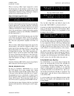
A M B I E N T A I R T E M P
= X X X . X ° F
Displays the Ambient Temperature at the time of the
fault.
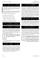
L E A D S Y S T E M I S
S Y S T E M N U M B E R X
Displays Local or Remote control selection.
C O N T R O L M O D E
L E A V I N G L I Q U I D
Displays the type of chilled liquid control; Leaving or
Return.
L E A D / L A G C O N T R O L
X X X X X X X X
Displays the type of lead/lag control; Manual System
1, Manual System 2 or Automatic. This is only select-
able on 2-system chillers.
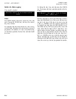
F A N C O N T R O L
D I S C H A R G E P R E S S U R E
This message does not apply to a YCWL chiller.
M A N U A L O V E R R I D E M O D E
X X X X X X X X X
Displays whether Manual Override was Enabled or
Disabled.
C U R R E N T F E E D B A C K
X X X X X X X X X X X X X X X X
Displays type of Current Feedback utilized.
S O F T S T A R T
X X X X X X X
Displays whether the optional European Soft Start was
installed and selected.
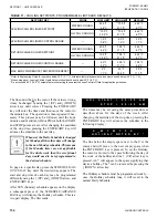
D I S C H A R G E P R E S S U R E
C U T O U T = X X X X P S I G
Displays the programmed Discharge Pressure Cutout.
S U C T I O N P R E S S U R E
C U T O U T = X X X X P S I G
Displays the programmed Suction Pressure Cutout.
L O W A M B I E N T T E M P
C U T O U T = X X X . X ° F
Displays the programmed Low Ambient Cutout.
L E A V I N G L I Q U I D T E M P
C U T O U T = X X X . X ° F
Displays the Leaving Liquid Temp. Cutout pro-
grammed.
Summary of Contents for YCWL0056SE
Page 4: ...FORM 201 26 NM1 ISSUE DATE 1 19 2018 JOHNSON CONTROLS 4 THIS PAGE INTENTIONALLY LEFT BLANK...
Page 30: ...FORM 201 26 NM1 ISSUE DATE 1 19 2018 JOHNSON CONTROLS 30 THIS PAGE INTENTIONALLY LEFT BLANK...
Page 146: ...FORM 201 26 NM1 ISSUE DATE 1 19 2018 JOHNSON CONTROLS 146 THIS PAGE INTENTIONALLY LEFT BLANK...
Page 154: ...FORM 201 26 NM1 ISSUE DATE 1 19 2018 JOHNSON CONTROLS 154 THIS PAGE INTENTIONALLY LEFT BLANK...
Page 168: ...FORM 201 26 NM1 ISSUE DATE 1 19 2018 JOHNSON CONTROLS 168 THIS PAGE INTENTIONALLY LEFT BLANK...
Page 186: ...FORM 201 26 NM1 ISSUE DATE 1 19 2018 JOHNSON CONTROLS 186 NOTES...


