background image

JOHNSON CONTROLS

300

FORM 201.23-NM2 

ISSUE DATE: 09/25/2020

SECTION 8 - MICROPANEL

Yorktalk 2 Communications

Received Data (Control Data)

The unit receives eight data values from the Micro-

Gateway or E-Link. The first four are analog values 

and the last four are digital values. These eight data 

values are used as control parameters when in RE-

MOTE mode. When the unit is in LOCAL mode, these 

eight values are ignored. If the unit receives no valid 

YorkTalk 2 transmission for 5 minutes it will revert 

back to all local control values. 

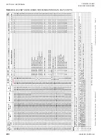
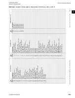
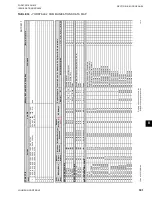
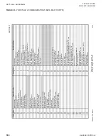
Table 33 on page 301


“Yorktalk 2 Communications Data Map” lists the con-

trol parameters. These values are found under feature 

54 in the MicroGateway or E-Link.

Transmitted Data

After receiving a valid transmission from the Micro-

Gateway or E-Link, the unit will transmit either op-

erational data or history buffer data depending on the 

“History Buffer Request” on ENG PAGE 10. Data 

must be transmitted for every page under feature 54. 

If there is no value to be sent to a particular page, a 

zero will be sent. 

Table 33 on page 301

 “Yorktalk 2 

Communications Data Map” shows the data values and 

page listings for this unit.

The latest point map information is listed 

on the Johnson Controls Equipment In-

tegration website.

Summary of Contents for YCIV Series

Page 1: ...0 260 TONS AIR COOLED SCREW LIQUID CHILLERS E V HIGH EFFICIENCY AND S P STANDARD EFFICIENCY AIR COOLED SCREW LIQUID CHILLERS INSTALLATION OPERATION MAINTENANCE Supersedes 201 23 NM2 919 Form 201 23 NM...

Page 2: ...this document and any referenced materials This in dividual shall also be familiar with and comply with all applicable industry and governmental standards and regulations pertaining to the task in que...

Page 3: ...ch operating temperatures of over 150 C 300 F DO NOT open panel doors during operation Assure the inductor is cool whenever working near the inductor with power OFF In complying with Johnson Controls...

Page 4: ...400 415 3 50 58 575 3 60 Design Series REVISION NOTES Revisions made to this document are indicated in the following table These revisions are to technical information and any other changes in spellin...

Page 5: ...Moving the Chiller 30 Unit Removal from Shipping Container 30 Lifting Using Lugs 30 Lifting Using Shackles 30 SECTION 4 INSTALLATION 33 Location Requirements 33 Outdoor Installations 33 Indoor Install...

Page 6: ...Components 184 Compressor Components 186 Chiller Electronic Components 187 Chiller Configuration Jumpers 195 VSD Logic to Chiller Microprocessor Board RS 485 Communication Configuration Jumpers 196 Ma...

Page 7: ...erride Key 270 Print Key 271 Service Key 274 System Switches Key 280 Serial Number Programming 281 Enabling Optimized High IPLV Mode 282 Unit Setup Mode 283 Default Programmable Values 284 Serial Port...

Page 8: ...Diagram 161 FIGURE 23 Process and Instrumentation Diagram 162 FIGURE 24 Component Locations 163 FIGURE 25 Control and VSD Cabinet Components 164 FIGURE 26 Chiller Control Board Relay Boards Microgatew...

Page 9: ...omms and System Open Close LED s 210 FIGURE 57 Condenser Fan Locations 212 FIGURE 58 Standard IPLV Fan Control 213 FIGURE 59 High IPLV Fan Control 213 FIGURE 60 Microboard 331 03478 xxx 230 FIGURE 61...

Page 10: ...ssure Cutout 237 TABLE 18 Start Inhibit Sensor Thresholds 239 TABLE 19 Sensor Min Max Outputs 247 TABLE 20 Setpoint Limits 259 TABLE 21 Programmable Operating Parameters 262 TABLE 22 Printout Types 27...

Page 11: ...ment unless labor or extended warranty has been purchased as part of the contract The warranty is limited to parts only replacement and shipping of any faulty part or sub assembly which has failed due...

Page 12: ...dures These are issued for guidance only and they do not take precedence over the above stated individual responsibility and or local safety regulations This manual and any other document supplied wit...

Page 13: ...metal edges Reasonable care should be taken when working in contact with the coils to avoid the risk of minor abrasions and lacerations The use of gloves is recommended Frame rails brakes and other co...

Page 14: ...JOHNSON CONTROLS 14 FORM 201 23 NM2 ISSUE DATE 09 25 2020 THIS PAGE INTENTIONALLY LEFT BLANK...

Page 15: ...uit General System Description The Latitude YCIV Air Cooled Chiller line combines the best of modern screw compressor design with the latest technology in variable speed drives The result is superior...

Page 16: ...and reliable performance Capacity control is achieved by stepless VSD speed changes No slide valve is re quired Smooth capacity control is achieved between 10 and 100 of chiller capacity in most opera...

Page 17: ...ambient and insulated with 3 4 in 19 mm flexible closed cell insulation The water nozzles are provided with grooves for me chanical couplings and should be insulated by the con tractor after pipe inst...

Page 18: ...noid is ON The economizer solenoid valve will typically be on most of the time When the economizer solenoid is OFF the liquid level will vary greatly as the Drain and Feed Valves directly affect the l...

Page 19: ...tandard utilizing ei ther a lockable circuit breaker or terminal block 115 VAC control transformer VSD fan contactors ON OFF unit switch microcomputer keypad and display Chiller Control and VSD Logic...

Page 20: ...s Keypad An operator keypad allows complete control of the system from a central location The keypad utilizes an overlay to allow use in 5 languages The keypad is a color coded 36 button sealed keypad...

Page 21: ...of the drive consists of a group of electrolytic filter capacitors C1 C6 This capacitor bank effectively smoothes the ripple voltage from the AC to DC rectifier while simultaneously pro viding a larg...

Page 22: ...ancillary sensors and boards are used to send information back to the VSD Logic Board Each IGBT Power Module within the DC to AC inverter section contains a thermistor heatsink temperature sensor to...

Page 23: ...for all environments The system designer can take steps to inhibit coil cor rosion in harsh applications and enhance equipment life by choosing from these options based on project design parameters a...

Page 24: ...ecial relief valves per Chicago code Factory mounted Pressure Relief CE PED Service Valve Kit Each relief valve is mounted on a sealable ball valve to aid maintenance Factory mounted Circuit Breaker P...

Page 25: ...d IPLV V High Efficiency High Ambient Unit Optimized IPLV H Standard Efficiency Optimized IPLV ARI Only REF Refrigerant PIN 10 A R 134a VOLTS Voltage PIN 11 12 17 200 3 60 28 230 3 60 40 380 3 60 46 4...

Page 26: ...Control Panel required Q Special Remote Control Panel required SEQ Sequence Kit PIN 28 X No Sequence Kit required S Sequence Control Automatic Lead Transfer seq Q Special Sequence Kit required TEMP W...

Page 27: ...cial Cooler requirements PIN44 Connections PIN 44 L Handed cooler left view from control panel end R Handed cooler right view from control panel end Q Special quote COILS Coils PIN 45 X Aluminum Coils...

Page 28: ...RANTY Warranty PIN 55 For Marketing Purposes REFRIGERANT WTY Refrigerant Wty PIN 56 For Marketing Purposes SHIP Ship Instructions PIN 57 X No Containerization Required with Shipping Bag A Buy American...

Page 29: ...oils and fins from potential damage and corrosion particularly where building work is in progress The unit should be stored in a location where there is minimal activity in order to limit the risk of...

Page 30: ...the unit until the lifting locations are outside of the container Place 4 X 4 blocks of wood under the base rails of the unit Gently rest the unit on the blocks and remove the chains and lift truck 5...

Page 31: ...846 Y 92 7 Y 2355 Y 180 7 Y 4590 Y 284 9 Y 7235 3 COMPRESSOR MODELS 60 hz EFF 1 2 3 4 5 INCH METRIC INCH METRIC INCH METRIC INCH METRIC INCH METRIC 0267 HIGH Y 33 2 Y 843 8 Y 141 1 Y 3584 8 Y 238 6 Y...

Page 32: ...JOHNSON CONTROLS 32 FORM 201 23 NM2 ISSUE DATE 09 25 2020 THIS PAGE INTENTIONALLY LEFT BLANK...

Page 33: ...se rails This will allow vibration isolators to be fitted if required Isolators are recom mended for rooftop locations Any ductwork or attenuators fitted to the unit must not have a total static press...

Page 34: ...nit base is level A more detailed installation instruction is provided on Pages 164 through 169 for units shipped on or after June 15 2008 and Pages 170 through 174 for units shipped before June 15 20...

Page 35: ...aterials of carbon steel and copper The pH value of the water flowing through the evaporator must be kept in a range between 7 and 8 5 Pipework and fittings must be separately supported to prevent any...

Page 36: ...gure 7 FLANGE ATTACHMENT WELD FLANGE GROOVED ADAPTER LD29341 REFRIGERANT RELIEF VALVE PIPING The evaporator is protected against internal refrigerant overpressure by refrigerant relief valves A pressu...

Page 37: ...d to prevent side loading on the unit If the ducts from two or more fans are to be combined into a common duct back flow dampers should be fit ted in the individual fan ducts This will prevent re circ...

Page 38: ...or optional circuit breaker located in the panel using lug sizes detailed in SECTION 6 TECHNICAL DATA see Figure 26 on page 165 Figure 32 on page 171 and Figure 33 on page 172 Connect a ground wire f...

Page 39: ...d 2 4 These inputs require a dry con tact to start and stop the system System 1 3 remote dry contacts are connected between Terminals 2 and 15 of 1TB Figure 32 on page 171 and Figure 33 on page 172 an...

Page 40: ...JOHNSON CONTROLS 40 FORM 201 23 NM2 ISSUE DATE 09 25 2020 THIS PAGE INTENTIONALLY LEFT BLANK...

Page 41: ...ssure transducers Open the liquid line service valve and oil return line ball valve fully in each system Compressor Oil To add oil to a circuit connect a YORK hand oil pump Part No 470 10654 000 to th...

Page 42: ...ure sensor is coated with heat conductive compound Part No 013 00890 000 and is inserted to the bottom of the water outlet sensor well in the evaporator This sensor is part of the pump control freeze...

Page 43: ...fficient pressure for correct operation of the con densers and the lubrication system As discharge pressure rises the condenser fans operate in stages to control the pressure Verify that the fans oper...

Page 44: ...s maintained or shut down and will be subjected to sub freezing conditions it is critical to protect against evaporator and waterbox freeze dam age Johnson Controls recommends the following op tions i...

Page 45: ...rature sensor errors may result in poor refrigerant control and liquid over feed to the compressor In the unlikely event it is necessary to add oil con nect a YORK oil pump to the charging valve on th...

Page 46: ...with the flow switch for additional protection if the pump is turned off during chiller operation When ever the pump contacts are used the coil of the pump starter should be suppressed with an RC supp...

Page 47: ...__________________________ Remote Temperature Reset ___________________ Remote Current Reset _______________________ RemoteSoundLimit __________________________ LowAmbientCutout ______________________...

Page 48: ...overcharged system should be guarded against Evidence of overcharge is as follows a If a system is overcharged the discharge pressure will be higher than normal Normal discharge condensing pressure c...

Page 49: ...rheat _____ _____ F C Discharge superheat will typically run approx 28 to 30 F This can be checked on the micropanel display If the suction superheat drops very low or the economizer feeds liquid into...

Page 50: ...JOHNSON CONTROLS 50 FORM 201 23 NM2 ISSUE DATE 09 25 2020 THIS PAGE INTENTIONALLY LEFT BLANK...

Page 51: ...ATER PRESSURE DROP CHARTS SECTION 6 TECHNICAL DATA COOLER MODEL NUMBER YCIV 60 HZ A 0157 S P H B 0157 E V 0177 S P H E V 0187 S P H E V C 0197 E V 0207 E V 0227 E V D 0207 S P H 0227 S P H 0247 S P H...

Page 52: ...AL DATA SI UNITS WATER PRESSURE DROP CHARTS CONT D COOLER MODEL NUMBER YCIV 60 HZ A 0157 S P H B 0157 E V 0177 S P H E V 0187 S P H E V C 0197 E V 0207 E V 0227 E V D 0207 S P H 0227 S P H 0247 S P H...

Page 53: ...B C Pressure Drop Through Three and Four Circuit YCIV Evaporators ENGLISH UNITS Pressure Drop Through Three Circuit YCIV Evaporators EVAP MODEL NUMBER YCIV 60 HZ A 0267EA VA 0287SA PA HA 0287EA VA B 0...

Page 54: ...and Four Circuit YCIV Evaporators SIUNITS WATER PRESSURE DROP CHARTS CONT D Pressure Drop Through Three Circuit YCIV Evaporators EVAP MODEL NUMBER YCIV 60 HZ A 0267EA VA 0287SA PA HA 0287EA VA B 0307S...

Page 55: ...orator PROPYLENE GLYCOL ETHYLENE GLYCOL GLYCOL CORRECTION FACTORS A A B B 1 8 1 7 1 6 1 5 1 4 1 3 1 2 1 1 1 0 1 45 1 40 1 35 1 30 1 25 1 20 1 15 1 10 1 05 50 40 30 20 10 50 40 30 20 10 C C 10 8 6 4 2...

Page 56: ...E V 40 60 180 750 0 125 0227 S P H 40 60 180 800 0 125 0227 E V 40 60 180 750 0 125 0247 S P H 40 60 180 800 0 125 0247 E V 40 60 180 800 0 125 0267 S P H 40 60 180 800 0 125 0267 E V 40 60 250 1200...

Page 57: ...4 47 3 17 8 51 7 0227 S P H 4 4 15 6 11 4 50 5 17 8 51 7 0227 E V 4 4 15 6 11 4 47 3 17 8 51 7 0247 S P H 4 4 15 6 11 4 50 5 17 8 51 7 0247 E V 4 4 15 6 10 1 47 3 17 8 51 7 0267 S P H 4 4 15 6 11 4 50...

Page 58: ...2 2 2 2 2 2 Total Chiller Airflow cfm 104000 104000 117000 117000 130000 143000 156000 ULTRA QUIET FANS Fan Motor HP 2 2 2 2 2 2 2 Total Chiller Airflow cfm 104000 104000 117000 117000 130000 143000 1...

Page 59: ...r Ckt 1 Ckt 2 5 4 4 5 4 4 5 5 6 6 6 6 Low Noise Fans Fan Motor HP kWi 2 1 8 2 1 8 2 1 8 2 1 8 Total Chiller Airflow cfm 169000 182000 208000 234000 Ultra Quiet Fans Fan Motor HP kWi 2 1 50 2 1 50 2 1...

Page 60: ...Noise Fans Fan Motor hp 2 2 2 2 2 2 2 Total Chiller Airflow cfm 104000 117000 130000 130000 143000 156000 156000 Ultra Quiet Fans Fan Motor hp 2 2 2 2 2 2 2 Total Chiller Airflow cfm 104000 117000 130...

Page 61: ...17 17 17 Condenser Fans Number Ckt 1 Ckt 2 5 5 4 5 5 6 5 5 6 6 6 6 Low Noise Fans Fan Motor HP kWi 2 1 8 2 1 8 2 1 8 2 1 8 Total Chiller Airflow cfm 182000 208000 208000 234000 Ultra Quiet Fans Fan Mo...

Page 62: ...ow Noise Fans Fan Motor HP kWi 2 1 50 2 1 50 2 1 50 2 1 50 2 1 50 2 1 50 2 1 50 Total Chiller Airflow L s 49082 49082 55218 55218 61353 67488 73624 Ultra Quiet Fans Fan Motor HP kWi 2 1 50 2 1 50 2 1...

Page 63: ...3 3 3 Fins per meter 669 669 669 669 Condenser Fans Number Ckt 1 Ckt 2 5 4 4 5 5 4 5 5 6 6 6 6 Low Noise Fans Fan Motor HP kWi 2 1 50 2 1 50 2 1 50 2 1 50 Total Chiller Airflow L s 79768 85904 98176...

Page 64: ...und Fans Fan Motor HP kWi 2 1 50 2 1 50 2 1 50 2 1 50 2 1 50 2 1 50 2 1 50 Total Chiller Airflow L s 49082 55218 61353 61353 67488 73624 73624 Ultra Quiet Fans Fan Motor HP kWi 2 1 50 2 1 50 2 1 50 2...

Page 65: ...per meter 669 669 669 669 Condenser Fans Number Ckt 1 Ckt 2 05 05 04 05 05 06 05 05 06 06 06 06 Low Noise Fans Fan Motor HP kWi 2 1 50 2 1 50 2 1 50 2 1 50 Total Chiller Airflow L s 85904 98176 98176...

Page 66: ...23 NM2 ISSUE DATE 09 25 2020 SECTION 6 TECHNICAL DATA Figure 8 TWO COMPRESSOR WIRING DIAGRAM WITH CIRCUIT BREAKER Figure 9 TWO COMPRESSOR WIRING DIAGRAM WITH TERMINAL BLOCK ELECTRICAL DATA 2 Compress...

Page 67: ...VAPORATOR HEATER UNIT CONTROLS FIELD PROVIDED UNIT POWER SUPPLY VSD 1 VSD CONTROL PANEL LINE REACTOR VSD 3 VSD 2 CIRCUIT BREAKER GRD STANDARD CONTROL TRANSFORMER 3 COMPRESSOR POWER WIRING CONNECTIONS...

Page 68: ...0207 460 60 145 5 2 8 380 60 184 5 3 5 184 5 9 3 0227 460 60 162 5 2 8 380 60 205 5 3 5 205 5 9 3 0247 460 60 193 6 2 8 380 60 245 6 3 5 245 6 9 3 0267 460 60 191 6 2 8 380 60 242 6 3 5 242 6 9 3 YCIV...

Page 69: ...QTY FLA EA QTY FLA EA QTY FLA EA 120 4 2 8 152 4 3 5 152 4 9 3 105 4 2 8 133 4 3 5 133 4 9 3 120 4 2 8 152 4 3 5 152 4 9 3 162 4 2 8 206 4 3 5 206 4 9 3 162 5 2 8 205 5 3 5 205 5 9 3 160 5 2 8 203 5...

Page 70: ...RANGE LUGS PHASE 1 LUG WIRE RANGE 0157 460 60 2 2 600 KCM 2 2 0 500 KCM 380 60 2 2 600 KCM 2 2 0 500 KCM 3 2 600 KCM 3 3 0 400 KCM 0177 460 60 2 2 600 KCM 2 2 0 500 KCM 380 60 2 2 600 KCM 2 2 0 500 KC...

Page 71: ...JOHNSON CONTROLS 71 SECTION 6 TECHNICAL DATA FORM 201 23 NM2 ISSUE DATE 09 25 2020 THIS PAGE INTENTIONALLY LEFT BLANK...

Page 72: ...97 1 8 30 65 345 400 450 450 1 8 30 65 437 500 600 600 0207 1 8 30 65 362 450 500 500 1 8 30 65 458 600 600 600 0227 1 8 30 65 371 450 500 500 1 8 30 65 469 600 600 600 0247 1 8 30 65 424 500 600 600...

Page 73: ...22 600 700 700 539 600 700 700 606 700 800 800 HIGH EFFICIENCY YCIV_ _ _ _ E V SYSTEM 2 STD ULTRA QUIET COND FANS HIGH HEAD STATIC COND FANS TWO SPEED COND FANS COMPRESSOR CONDENSER FANS COMPRESSOR CO...

Page 74: ...LUGS PHASE 1 LUG WIRE RANGE 0157 460 60 2 2 600 KCM 2 2 0 500 KCM 380 60 2 2 600 KCM 2 2 0 500 KCM 3 2 600 KCM 3 3 0 400 KCM 0177 460 60 2 2 600 KCM 2 2 0 500 KCM 380 60 2 2 600 KCM 2 2 0 500 KCM 3 2...

Page 75: ...JOHNSON CONTROLS 75 SECTION 6 TECHNICAL DATA FORM 201 23 NM2 ISSUE DATE 09 25 2020 THIS PAGE INTENTIONALLY LEFT BLANK...

Page 76: ...30 65 624 700 800 800 676 800 0307 2 4 30 65 540 600 700 700 2 4 30 65 682 800 800 800 731 800 0357 2 4 30 65 607 700 800 800 2 4 30 65 766 1000 1000 1000 827 1000 0397 2 4 30 65 671 800 800 800 2 4 3...

Page 77: ...2 LUGS PHASE 1 LUG WIRE RANGE LUGS PHASE 1 LUG WIRE RANGE 4 2 600 KCM 4 4 0 500 KCM 800 800 4 2 600 KCM 4 4 0 500 KCM 4 2 600 KCM 4 4 0 500 KCM 800 800 4 2 600 KCM 4 4 0 500 KCM 4 2 600 KCM 4 4 0 500...

Page 78: ...5 2 8 137 5 2 8 380 60 173 5 3 5 173 5 9 3 173 5 3 5 0327 460 60 152 5 2 8 152 5 2 8 380 60 193 5 3 5 193 5 9 3 193 5 3 5 0357 460 60 181 6 2 8 181 6 2 8 380 60 229 6 3 5 229 6 9 3 229 6 3 5 YCIV S P...

Page 79: ...ction Field Wiring Lugs High Head High Static Fans Two Speed Cond Fans STD Terminal Block OPT Circuit Breaker Max Inverse Time Ckt Brkr Rat ing 2 Max Dual Element Fuse Size 2 Minimum Ckt Ampacity MCA...

Page 80: ...ontrols and evaporator heaters 8 System inrush current is less than RLA due to the use of York Variable Speed Drive technology Table 1 TYPICAL COMPRESSOR STARTING CURRENT FIRST FOUR SECONDS OF START U...

Page 81: ...JOHNSON CONTROLS 81 SECTION 6 TECHNICAL DATA FORM 201 23 NM2 ISSUE DATE 09 25 2020 THIS PAGE INTENTIONALLY LEFT BLANK...

Page 82: ...OHNSON CONTROLS 82 FORM 201 23 NM2 ISSUE DATE 09 25 2020 SECTION 6 TECHNICAL DATA Figure 12 ELEMENTARY CONTROL WIRING DIAGRAM 2 COMPRESSOR MODELS LD26907 ELECTRICAL WIRING DIAGRAMS 2 COMPRESSOR MODELS...

Page 83: ...JOHNSON CONTROLS 83 SECTION 6 TECHNICAL DATA FORM 201 23 NM2 ISSUE DATE 09 25 2020 6 FIGURE 12 ELEMENTARY CONTROL WIRING DIAGRAM 2 COMPRESSOR MODELS CONT D LD26908 035 19905 001 REV K SHT 1...

Page 84: ...NSON CONTROLS 84 FORM 201 23 NM2 ISSUE DATE 09 25 2020 SECTION 6 TECHNICAL DATA Figure 13 ELEMENTARY POWER WIRING DIAGRAM YCIV0157 0267 2 COMPRESSOR MODELS LD13678 LD26909 Elementary Power Wiring Diag...

Page 85: ...NSON CONTROLS 85 SECTION 6 TECHNICAL DATA FORM 201 23 NM2 ISSUE DATE 09 25 2020 6 FIGURE13 ELEMENTARYPOWER WIRING DIAGRAM YCIV0157 02672COMPRESSOR MODELS CONT D LD13679 LD26910 035 19905 002 REV J SHT...

Page 86: ...JOHNSON CONTROLS 86 FORM 201 23 NM2 ISSUE DATE 09 25 2020 SECTION 6 TECHNICAL DATA Figure 14 POWER WIRING CONNECTION DIAGRAM YCIV0157 0267 2 COMPRESSOR MODELS LD26912 Power Wiring Connection Diagram...

Page 87: ...JOHNSON CONTROLS 87 SECTION 6 TECHNICAL DATA FORM 201 23 NM2 ISSUE DATE 09 25 2020 6 FIGURE14 POWERWIRINGCONNECTIONDIAGRAM YCIV0157 02672COMPRESSORMODELS CONT D LD26911 035 19905 004 REV L SHT 1...

Page 88: ...OHNSON CONTROLS 88 FORM 201 23 NM2 ISSUE DATE 09 25 2020 SECTION 6 TECHNICAL DATA Figure 15 CONTROL WIRING CONNECTION DIAGRAM YCIV0157 0267 2 COMPRESSOR MODELS LD26913 Control Wiring Connection Diagra...

Page 89: ...JOHNSON CONTROLS 89 SECTION 6 TECHNICAL DATA FORM 201 23 NM2 ISSUE DATE 09 25 2020 6 FIGURE15 CONTROLWIRINGCONNECTIONDIAGRAM YCIV0157 02672COMPRESSORMODELS CONT D LD26914 035 19905 003 REV L SHT 1...

Page 90: ...JOHNSON CONTROLS 90 FORM 201 23 NM2 ISSUE DATE 09 25 2020 SECTION 6 TECHNICAL DATA LD26921 035 19905 003 REV L SHT 1 FIGURE15 CONTROLWIRINGCONNECTIONDIAGRAM YCIV0157 02672COMPRESSORMODELS CONT D...

Page 91: ...JOHNSON CONTROLS 91 SECTION 6 TECHNICAL DATA FORM 201 23 NM2 ISSUE DATE 09 25 2020 6 Figure 16 POWER ELEMENTARY WIRING DIAGRAM YCIV0157 0267 2 COMPRESSOR MODELS LD13081 Power Elementary Wiring Diagram...

Page 92: ...JOHNSON CONTROLS 92 FORM 201 23 NM2 ISSUE DATE 09 25 2020 SECTION 6 TECHNICAL DATA LD13082 FIGURE16 POWERELEMENTARYWIRINGDIAGRAM YCIV0157 02672COMPRESSORMODELS CONT D...

Page 93: ...JOHNSON CONTROLS 93 SECTION 6 TECHNICAL DATA FORM 201 23 NM2 ISSUE DATE 09 25 2020 6 LD10519 Location Label 2 Compressor Models...

Page 94: ...JOHNSON CONTROLS 94 FORM 201 23 NM2 ISSUE DATE 09 25 2020 SECTION 6 TECHNICAL DATA Panel Layout 2 Compressor Models...

Page 95: ...JOHNSON CONTROLS 95 SECTION 6 TECHNICAL DATA FORM 201 23 NM2 ISSUE DATE 09 25 2020 THIS PAGE INTENTIONALLY LEFT BLANK...

Page 96: ...SON CONTROLS 96 FORM 201 23 NM2 ISSUE DATE 09 25 2020 SECTION 6 TECHNICAL DATA Figure 17 CONTROL ELEMENTARY DIAGRAM YCIV0257 0397 3 COMPRESSOR MODELS LD26915 ELECTRICAL WIRING DIAGRAMS 3 COMPRESSOR MO...

Page 97: ...JOHNSON CONTROLS 97 SECTION 6 TECHNICAL DATA FORM 201 23 NM2 ISSUE DATE 09 25 2020 6 LD26916 035 20326 001 REV I SHT 1 FIGURE 17 CONTROL ELEMENTARY DIAGRAM YCIV0257 0397 3 COMPRESSOR MODELS CONT D...

Page 98: ...JOHNSON CONTROLS 98 FORM 201 23 NM2 ISSUE DATE 09 25 2020 SECTION 6 TECHNICAL DATA FIGURE 17 CONTROL ELEMENTARY DIAGRAM YCIV0257 0397 3 COMPRESSOR MODELS CONT D LD26917...

Page 99: ...JOHNSON CONTROLS 99 SECTION 6 TECHNICAL DATA FORM 201 23 NM2 ISSUE DATE 09 25 2020 6 FIGURE 17 CONTROL ELEMENTARY DIAGRAM YCIV0257 0397 3 COMPRESSOR MODELS CONT D LD26918 035 20326 002 REV H SHT 1...

Page 100: ...JOHNSON CONTROLS 100 FORM 201 23 NM2 ISSUE DATE 09 25 2020 SECTION 6 TECHNICAL DATA LD26919 Figure 18 POWER ELEMENTARY DIAGRAM YCIV0257 0397 3 COMPRESSOR MODELS Power Elementary Diagram...

Page 101: ...JOHNSON CONTROLS 101 SECTION 6 TECHNICAL DATA FORM 201 23 NM2 ISSUE DATE 09 25 2020 6 LD26920 035 23260 003 REV F SHT 1 FIGURE 18 POWER ELEMENTARY DIAGRAM YCIV0257 0397 3 COMPRESSOR MODELS CONT D...

Page 102: ...HNSON CONTROLS 102 FORM 201 23 NM2 ISSUE DATE 09 25 2020 SECTION 6 TECHNICAL DATA Figure 19 CONTROL WIRING CONNECTION DIAGRAM YCIV0257 0397 3 COMPRESSOR MODELS Control Wiring Connection Diagram LD1309...

Page 103: ...JOHNSON CONTROLS 103 SECTION 6 TECHNICAL DATA FORM 201 23 NM2 ISSUE DATE 09 25 2020 6 FIGURE 19 CONTROL WIRING CONNECTION DIAGRAM YCIV0257 0397 3 COMPRESSOR MODELS CONT D LD13091...

Page 104: ...JOHNSON CONTROLS 104 FORM 201 23 NM2 ISSUE DATE 09 25 2020 SECTION 6 TECHNICAL DATA LD13092 FIGURE 19 CONTROL WIRING CONNECTION DIAGRAM YCIV0257 0397 3 COMPRESSOR MODELS CONT D...

Page 105: ...JOHNSON CONTROLS 105 SECTION 6 TECHNICAL DATA FORM 201 23 NM2 ISSUE DATE 09 25 2020 THIS PAGE INTENTIONALLY LEFT BLANK...

Page 106: ...JOHNSON CONTROLS 106 FORM 201 23 NM2 ISSUE DATE 09 25 2020 SECTION 6 TECHNICAL DATA Figure 20 POWER WIRING CONNECTION DIAGRAM YCIV1050 1500 3 COMPRESSOR MODELS Power Wiring Connection Diagram LD26922...

Page 107: ...JOHNSON CONTROLS 107 SECTION 6 TECHNICAL DATA FORM 201 23 NM2 ISSUE DATE 09 25 2020 6 FIGURE20 POWERWIRINGCONNECTIONDIAGRAM YCIV1050 15003COMPRESSORMODELS CONT D LD26923 035 20326 005 REV H SHT 1...

Page 108: ...JOHNSON CONTROLS 108 FORM 201 23 NM2 ISSUE DATE 09 25 2020 SECTION 6 TECHNICAL DATA LD13097 Figure 21 POWER ELEMENTARY DIAGRAM YCIV0257 0397 3 COMPRESSOR MODELS Power Elementary Diagram...

Page 109: ...JOHNSON CONTROLS 109 SECTION 6 TECHNICAL DATA FORM 201 23 NM2 ISSUE DATE 09 25 2020 6 LD13098 FIGURE 21 POWER ELEMENTARY DIAGRAM YCIV0257 0397 3 COMPRESSOR MODELS CONT D...

Page 110: ...JOHNSON CONTROLS 110 FORM 201 23 NM2 ISSUE DATE 09 25 2020 SECTION 6 TECHNICAL DATA Location Label 3 Compressor Models LD13096...

Page 111: ...JOHNSON CONTROLS 111 SECTION 6 TECHNICAL DATA FORM 201 23 NM2 ISSUE DATE 09 25 2020 6 LD13099 Panel Layout 3 Compressor Models...

Page 112: ...ration or air circulation ensures rated performance reliable operation and ease of maintenance Site restrictions may compromise minimum clearances indi cated below resulting in unpredictable airflow p...

Page 113: ...ND 3 COMPRESSOR ENGLISH CONT D 33 5 16 103 3 8 80 230 101 5 8 50 50 5 16 9 1 8 93 15 16 1 5 16 TYP X G C Y 3 RIGGING HOLES EACH SIDE 3 X 2 10 WATER OUTLET 10 WATER INLET VIEW D D X G C Z D D A A 5 8 M...

Page 114: ...ce of free of obstructions including snow for winter operation or air circulation ensures rated performance reliable operation and ease of maintenance Site restrictions may compromise minimum clearanc...

Page 115: ...OMPRESSOR ENGLISH CONT D POWER SINGLE POINT WITH TERMINAL BLOCK X G C Y VIEW D D B 33 5 16 103 5 16 A 112 13 16 84 1 2 93 15 16 D D X G C Z 10 WATER INLET 10 WATER OUTLET A A 9 1 8 50 5 16 50 86 5 16...

Page 116: ...cluding snow for winter operation or air circulation ensures rated performance reliable operation and ease of maintenance Site restrictions may compromise minimum clearances indi cated below resulting...

Page 117: ...E POINT WITH TERMINAL BLOCK X G C Y VIEW D D 274 33 5 16 103 5 16 88 D C 93 15 16 D D X Z 10 WATER INLET 10 WATER OUTLET A A 9 1 8 50 5 16 50 86 5 16 69 11 16 1 5 16 TYP 5 8 MOUNTING HOLES TYP 3 RIGGI...

Page 118: ...or air circulation ensures rated performance reliable operation and ease of maintenance Site restrictions may compromise minimum clearances indi cated below resulting in unpredictable airflow patterns...

Page 119: ...CONT D POWER SINGLE POINT WITH TERMINAL BLOCK CONTROL PANEL VIEW D D 9 1 8 50 5 16 37 13 16 64 3 16 49 3 16 60 318 33 5 16 92 11 16 180 11 16 284 7 8 112 5 16 85 5 8 10 WATER OUTLET 10 WATER INLET A A...

Page 120: ...ion ensures rated performance reliable operation and ease of maintenance Site restrictions may compromise minimum clearances indi cated below resulting in unpredictable airflow patterns and possible d...

Page 121: ...LOCK CONTROL PANEL VIEW D D 9 1 8 50 5 16 37 13 16 64 3 16 49 3 16 60 318 33 5 16 92 11 16 180 11 16 284 7 8 113 5 16 79 1 8 10 WATER OUTLET 10 WATER INLET A A D D 93 15 16 5 8 MOUNTING HOLES TYP 4 RI...

Page 122: ...ted performance reliable operation and ease of maintenance Site restrictions may compromise minimum clearances indi cated below resulting in unpredictable airflow patterns and possible diminished perf...

Page 123: ...RESSOR ENGLISH CONT D 45 5 16 29 7 8 17 5 8 A A X G C Z D D 93 15 16 CONTROL PANEL 377 3 16 197 13 16 14 5 8 141 1 8 238 5 8 357 33 3 16 10 WATER INLET 10 WATER OUTLET 4 RIGGING HOLES EACH SIDE 3 X 2...

Page 124: ...operation and ease of maintenance Site restrictions may compromise minimum clearances indi cated below resulting in unpredictable airflow patterns and possible diminished performance Johnson Controls...

Page 125: ...LISH CONT D 50 5 16 50 76 99 19 53 3 8 9 1 8 1 5 16 TYP 7 5 8 17 5 8 29 7 8 93 15 16 D D X G C Z X G C Y CONTROL PANEL ORIGIN A A 421 1 4 123 11 16 216 11 16 320 1 2 401 37 3 16 197 13 16 14 5 8 10 WA...

Page 126: ...e operation and ease of maintenance Site restrictions may compromise minimum clearances indi cated below resulting in unpredictable airflow patterns and possible diminished performance Johnson Control...

Page 127: ...PRESSOR ENGLISH CONT D 45 5 16 26 3 8 16 3 16 A A X G C Z D D 93 15 16 CONTROL PANEL 377 3 16 197 13 16 15 141 1 8 238 5 8 357 33 3 16 10 WATER INLET 10 WATER OUTLET 4 RIGGING HOLES EACH SIDE 3 X 2 70...

Page 128: ...reliable operation and ease of maintenance Site restrictions may compromise minimum clearances indi cated below resulting in unpredictable airflow patterns and possible diminished performance Johnson...

Page 129: ...LISH CONT D 50 5 16 50 76 99 74 1 8 53 3 8 9 1 8 1 5 16 TYP 6 7 8 18 3 16 25 1 8 93 15 16 D D X G C Z X G C Y CONTROL PANEL ORIGIN A A 421 1 4 120 11 16 216 11 16 320 1 2 401 33 3 16 197 13 16 15 10 W...

Page 130: ...reliable operation and ease of maintenance Site restrictions may compromise minimum clearances indi cated below resulting in unpredictable airflow patterns and possible diminished performance Johnson...

Page 131: ...SH CONT D 93 15 16 6 7 8 CONTROL PANEL ORIGIN 53 3 8 9 1 8 50 5 16 50 76 112 11 16 19 VIEW D D 3 4 MOUNTING HOLES TYP 15 197 13 16 120 11 16 33 3 16 217 13 16 328 1 8 445 465 3 16 18 3 16 28 3 8 A A D...

Page 132: ...DATE 09 25 2020 SECTION 6 TECHNICAL DATA TECHNICAL DATA CLEARANCES NOTES 1 No obstructions allowed above the unit 2 Only one adjacent wall may be higher than the unit 3 Adjacent units should be 10 fee...

Page 133: ...77S P H LEFT L 9 1 86 8 59 4 86 8 109 4 86 8 211 86 8 Al Fin Coils 1720 1614 1667 1609 Cu Fin Coils 1720 1726 2011 1951 RS LS1 Al Fin Coils 1898 1792 1667 1609 RS LS1 Cu Fin Coils 1898 1905 2011 1951...

Page 134: ...4 86 8 Al Fin Coils 1728 1680 1768 1523 959 Cu Fin Coils 1728 1801 2108 1903 1120 RS LS1 Al Fin Coils 1907 1858 1768 1523 959 RS LS1 Cu Fin Coils 1907 1980 2108 1903 1120 RIGHT R 9 1 1 3 59 4 1 3 109...

Page 135: ...84 9 86 8 368 86 8 Al Fin Coils 1753 1585 1821 1810 2123 1175 Cu Fin Coils 1775 1757 2165 2156 2467 1347 RS LS1 Al Fin Coils 1929 1761 1821 1810 2189 1462 RS LS1 Cu Fin Coils 1885 1933 2165 2156 2533...

Page 136: ...oils 1753 1596 2540 2632 2540 1151 946 Cu Fin Coils 1775 1715 2824 3018 2926 1435 1065 RS LS1 Al Fin Coils 1929 1773 2540 2632 2540 1327 1122 RS LS1 Cu Fin Coils 1951 1892 2824 3018 2926 1612 1241 039...

Page 137: ...4 86 8 Al Fin Coils 1698 1559 1559 1274 774 Cu Fin Coils 1698 1680 1898 1653 935 RS LS1 Al Fin Coils 1876 1737 1559 1274 774 RS LS1 Cu Fin Coils 1876 1858 1898 1653 935 RIGHT R 9 1 1 3 59 4 1 3 109 4...

Page 138: ...u Fin Coils 1720 1704 1323 1270 1442 1193 RS LS1 Al Fin Coils 1898 1792 1082 994 1093 952 RS LS1 Cu Fin Coils 1898 1883 1323 1270 1442 1193 RIGHT R 9 1 1 3 59 4 1 3 97 2 1 3 161 4 1 3 210 6 1 3 307 9...

Page 139: ...Fin Coils 1775 1757 2165 2185 2507 1347 RS LS1 Al Fin Coils 1929 1761 1821 1839 2229 1396 RS LS1 Cu Fin Coils 1951 1933 2165 2185 2573 1634 RIGHT R 9 1 1 3 58 1 1 3 111 1 1 3 204 7 1 3 284 9 1 3 368 1...

Page 140: ...1 928 Cu Fin Coils 1775 1715 2824 3018 2926 1435 1047 RS LS1 Al Fin Coils 1929 1773 2540 2632 2540 1327 1105 RS LS1 Cu Fin Coils 1951 1892 2824 3018 2926 1612 1224 0357E V LEFT L 9 1 86 8 59 4 86 8 10...

Page 141: ...FT L 230 2204 1510 2204 2780 2204 5360 2204 Al Fin Coils 780 732 756 730 Cu Fin Coils 780 783 912 885 RS LS1 Al Fin Coils 861 813 756 730 RS LS1 Cu Fin Coils 861 864 912 885 RIGHT R 230 32 1510 32 278...

Page 142: ...4 Al Fin Coils 784 762 802 691 435 Cu Fin Coils 784 817 956 863 508 RS LS1 Al Fin Coils 865 843 802 691 435 RS LS1 Cu Fin Coils 865 898 956 863 508 RIGHT R 230 32 1510 32 2780 32 4970 32 6740 32 Al Fi...

Page 143: ...in Coils 795 719 826 821 963 533 Cu Fin Coils 805 797 982 978 1119 611 RS LS1 Al Fin Coils 875 799 826 821 993 663 RS LS1 Cu Fin Coils 855 877 982 978 1149 741 RIGHT R 230 32 1475 32 2823 32 5199 32 7...

Page 144: ...194 1152 522 429 Cu Fin Coils 805 778 1281 1369 1327 651 483 RS LS1 Al Fin Coils 875 804 1152 1194 1152 602 509 RS LS1 Cu Fin Coils 885 858 1281 1369 1327 731 563 0397S P H LEFT L 230 2204 1510 2204 2...

Page 145: ...2204 4970 2204 6740 2204 Al Fin Coils 770 707 707 578 351 Cu Fin Coils 770 762 861 750 424 RS LS1 Al Fin Coils 851 788 707 578 351 RS LS1 Cu Fin Coils 851 843 861 750 424 RIGHT R 230 32 1510 32 2780...

Page 146: ...780 732 491 451 496 432 Cu Fin Coils 780 773 600 576 654 541 RS LS1 Al Fin Coils 861 813 491 451 496 432 RS LS1 Cu Fin Coils 861 854 600 576 654 541 RIGHT R 230 32 1510 32 2470 32 4100 32 5350 32 782...

Page 147: ...4 981 533 Cu Fin Coils 805 797 982 991 1137 611 RS LS1 Al Fin Coils 875 799 826 834 1011 633 RS LS1 Cu Fin Coils 885 877 982 991 1167 741 RIGHT R 230 32 1475 32 2823 32 5199 32 7236 32 9346 32 Al Fin...

Page 148: ...194 1152 522 421 Cu Fin Coils 805 778 1281 1369 1327 651 475 RS LS1 Al Fin Coils 875 804 1152 1194 1152 602 501 RS LS1 Cu Fin Coils 885 858 1281 1369 1327 731 555 0357E V 163 LEFT L 230 2204 1510 2204...

Page 149: ...ITH GREEN 029 24583 012 CIP C 2650 RED WITH RED 029 25334 012 C2P 1D 2720 WHITE 029 24583 013 CIP C 2935 RED WITH GREEN 029 25334 013 C2P 1D 3570N GRAY iRED 029 24584 001 ND C YELLOW 029 25335 001 RD...

Page 150: ...ABLE PLATE OLTING OR ANCHORING MOUNT TO SUPPORT STRUCTURE WITH A MIN 2 A CONCRETE ANCHORS D FOR 50 OVER TRAVEL STALLATION INSTRUCTIONS RATED DEFLECTION IN COLOR CODE JCI PART NUMBER 1 02 BLACK 1 32 DK...

Page 151: ...out as re quired leveling all isolator bases to the same elevation 1 4 inch maximum difference can be tolerated 4 Bolt or anchor all isolators to supporting structure utilizing base slotted holes C 5...

Page 152: ...1 25 1 75 RATED PACITY LBS RATED DEFLECTION IN DURO 5 JCI PART NUMBER 135 0 5 30 170 0 5 40 240 0 5 50 380 0 5 60 550 0 5 70 ATED PACITY LBS RATED DEFLECTION IN DURO 5 JCI PART NUMBER 35 0 4 30 45 0...

Page 153: ...3 Set isolators on floor housekeeping pad or sub base ensuring that all isolator centerlines match the equipment mounting holes The VMC group recommends that the isolator base A be in stalled on a lev...

Page 154: ...2 5 8 11UNC TYP 4 2 3 4 3 4 7 8 1 1 8 3 8 GAP 5 1 2 LIMIT STOP NUT NOTES 1 ALL DIMENSIONS ARE IN INCHES INTERPRET PER ANSI Y14 2 STANDARD FINISH HOUSING POWDER COATED COLOR BLACK SPRING POWDER COATED...

Page 155: ...d over the isola tors 6 With all shims E in place position equipment on top of plate A of isolator Bolt equipment securely to top plate of isolator using a minimum of 2 5 8 UNC A325 grade 5 SAE bolts...

Page 156: ...014 Value is de rated by 15 Notes Illustration above shows a SLRS 4 C2 4 Springs SLRS 8 2 and C2 have one spring and SLRS 2 C2 has two springs SLRS 6 C2 has six springs and SLRS 9 C2 has nine springs...

Page 157: ...t Bolt Vertical Limit Stops Out of contact during normal operation Non Skid Neoprene Pad Pad can be removed if mounts are welded into position Enclosed Steel Housing Internal Neoprene Acoustical Pad L...

Page 158: ...8 8 7 9 101 6 127 0 1 2 13x1 13 ND DS 85 7 69 9 158 8 7 9 101 6 127 0 1 2 13x1 13 PIN 54 N WEIGHT RANGE LB WEIGHT RANGE KG COLOR YORK P N YORK P N Up to 751 Up to 341 ND C Yellow 029 24584 001 751 165...

Page 159: ...lue 029 24583 004 851 1064 386 483 CIP B 1250 Gray 029 24583 005 1064 1404 483 637 CIP B 1650 Black 029 24583 006 FOR UNITS WITH ANY LOAD POINT ABOVE 1404 LB 637 KG Up to 851 Up to 386 CIP C 1000 Blac...

Page 160: ...gs and the equipment is raised free of the spacer blocks or shims Remove the blocks or shims 8 Turn the leveling bolt of all mountings in either direction in order to level the installation 9 Tighten...

Page 161: ...Pressure Liquid High Pressure Vapor Oil Low Pressure Liquid Medium Pressure Vapor Economizer Added to some models COMPRESSOR Stopper Motor Valve Angle Stop Valve M3 S Air Entering Compressor R 22 Ref...

Page 162: ...URE LOAD LIMITING HIGH TEMPERATURE CUTOUT LOW PRESSURE CUTOUT CHT DP DV HPL HTC LPC LOW TEMPERATURE CUTOUT HIGH PRESSURE CUTOUT HEATER LTC HPC HTR SOLENOID VALVE BALL VALVE RELIEF VALVE STOP VALVE ANG...

Page 163: ...6 TECHNICAL DATA FORM 201 23 NM2 ISSUE DATE 09 25 2020 6 COMPONENT LOCATIONS Figure 24 COMPONENT LOCATIONS KEYPAD DISPLAY PANEL DOOR CHILLER DISPLAY ELECTRICAL PANEL FANS CONDENSER COIL FILTER DRIER...

Page 164: ...JOHNSON CONTROLS 164 FORM 201 23 NM2 ISSUE DATE 09 25 2020 SECTION 6 TECHNICAL DATA Figure 25 CONTROL AND VSD CABINET COMPONENTS COMPONENT LOCATIONS CONT D LD10578...

Page 165: ...NT D Figure 26 CHILLER CONTROL BOARD RELAY BOARDS MICROGATEWAY AND OPTIONAL CIRCUIT BREAKER LD10579 MICROGATEWAY OPTIONAL CHILLER CONTROL BOARD RELAY BOARD 1 RELAY BOARD 2 OPTIONAL CIRCUIT BREAKER Sta...

Page 166: ...TECHNICAL DATA Figure 27 CHILLER CONTROL BOARD RELAY BOARDS AND MICROGATEWAY 2 COMPRESSOR COMPONENT LOCATIONS CONT D LD10580 CHILLER CONTROL BOARD MICROGATEWAY OPTIONAL RELAY BOARD 1 RELAY BOARD 2 RS...

Page 167: ...3 NM2 ISSUE DATE 09 25 2020 6 Figure 28 CHILLER CONTROL BOARD RELAY BOARDS AND MICROGATEWAY 3 COMPRESSOR COMPONENT LOCATIONS CONT D 50069 CHILLER CONTROL BOARD RELAY BOARD 1 RELAY BOARD 2 RELAY BOARD...

Page 168: ...JOHNSON CONTROLS 168 FORM 201 23 NM2 ISSUE DATE 09 25 2020 SECTION 6 TECHNICAL DATA Figure 29 VSD LOGIC BOARD LD10582 COMPONENT LOCATIONS CONT D VSD LOGIC BOARD SCR TRIGGER BOARD...

Page 169: ...2 ISSUE DATE 09 25 2020 6 Figure 30 VSD LOGIC BOARD ORIGINAL OBSOLETE P N 031 02477 000 LD10590 COMPONENT LOCATIONS CONT D MADE IN THE USA YORK R86 COMPR 4 Over Load Adjust R42 COMPR 3 Over Load Adjus...

Page 170: ...2020 SECTION 6 TECHNICAL DATA Figure 31 VSD LOGIC BOARD NEW P N 031 02507 XXX COMPONENT LOCATIONS CONT D A S U E H T N I E D A M LD13119 R86 COMPR 4 Over Load Adjust R42 COMPR 3 Over Load Adjust R64...

Page 171: ...IRCUIT BREAKER Standard Unit will have terminal blocks FLASH TANK FEED AND DRAIN VALVE CONTROLLER CONTROL AND VSD CABINET COOLING COIL CONTROL AND VSD CABINET COOLING FAN 1TB TERMINAL BLOCK 10T TRANSF...

Page 172: ...NSFORMER OPTIONAL CIRCUIT BREAKER Standard Unit will have terminal blocks CONTROL AND VSD CABINET COOLING COIL CONTROL AND VSD CABINET COOLING FANS 10T TRANSFORMER INPUT POWER TO THE CHILLER CONNECTS...

Page 173: ...CHNICAL DATA FORM 201 23 NM2 ISSUE DATE 09 25 2020 6 Figure 34 FAN CONTACTORS AND 3T TRANSFORMER 2 COMPRESSOR COMPONENT LOCATIONS CONT D LD10584 FAN CONTACTORS 4CR 9CR 3T TRANSFORMER 24VAC to SCR Gate...

Page 174: ...SON CONTROLS 174 FORM 201 23 NM2 ISSUE DATE 09 25 2020 SECTION 6 TECHNICAL DATA Figure 35 FAN CONTACTORS 3 COMPRESSOR COMPONENT LOCATIONS CONT D 50072 FAN CONTACTORS 4 5 6 7 8 9 11 12 13CR 3T TRANSFOR...

Page 175: ...FU 10T and 11T 20 FU Relay Board 1 21 FU Relay Board 2 COOLING FAN 4 9 FU FUSES and 14 16 FU FUSES 4 6 FU TB 1 3 SCR Trigger Board 7 9 FU Sys 1 Fans 14 16 FU Sys 2 Fans TRANSIENT SUPPRESSOR BOARD 3 P...

Page 176: ...9CR 3T VSD LOGIC and SCR TRIGGER BOARD 24 VAC SUPPLY TRANSFORMER CURRENT TRANSFORMERS SNUBBER CAPS C7 C12 BUS ISOLATOR BOARD FEEDS VSD LOGIC BOARD SCR TRIGGER BOARD IGBT MODULES SCR DIODE MODULES 1RES...

Page 177: ...S 4CR 9CR AND 11CR 13 CR 3T VSD LOGIC AND SCR TRIGGER BOARD 24 VAC SUPPLY TRANSFORMER CURRENT TRANSFORMERS SNUBBER CAPS C7 C12 SCR TRIGGER BOARD SCR DIODE MODULES 1RES AND 2RES BUS CAPACITOR BANK EQUA...

Page 178: ...HNICAL DATA Figure 39 VSD COMPONENTS 2 COMPRESSOR LD10587 FAN RELAYS CURRENT TRANSFORMERS C13 C17 COOLING FANS 1L LINE INDUCTOR CABINET COOLING COIL TRANSIENT SUPPRESSOR BOARD W 11FU 12FU AND 13 FU FU...

Page 179: ...ELAYS CURRENT TRANSFORMERS C14 C13 12 9 8 7 6 5 4 COOLING FAN LINE INDUCTORS CABINET COOLING COIL TRANSIENT SUPPRESSOR BOARD W 11FU 12FU AND 13 FU FUSES 3 Phase Input 1 1 1 1 1 1 1 2 2 2 2 2 2 2 SNUBB...

Page 180: ...AL DATA Figure 41 INVERTER POWER COMPONENTS 2 COMPRESSOR LD10588 COMPONENT LOCATIONS CONT D The line inductor will reach operating temperatures of over 300 F Do not open panel doors during operation A...

Page 181: ...JOHNSON CONTROLS 181 SECTION 6 TECHNICAL DATA FORM 201 23 NM2 ISSUE DATE 09 25 2020 6 Figure 42 INVERTER POWER COMPONENTS 3 COMPRESSOR COMPONENT LOCATIONS CONT D 50077 SCR TRIGGER BOARD...

Page 182: ...VERTER POWER COMPONENTS LD10592 COMPONENT LOCATIONS CONT D LD10591 IGBT s IGBT s IGBT s WATER COOLED HEAT SINK SCR DIODE MODULE SCR DIODE MODULES 1RES and 2RES BUS CAPACITORS BANK EQUALIZING BLEEDER R...

Page 183: ...E 43 INVERTER POWER COMPONENTS CONT D LAMINATED BUS STRUCTURE BUS FILTER CAPACITORS IGBT GATE DRIVER BOARD IGBT WATER COOLED HEAT SINK IGBT s IGBT s SCR DIODE MODULES SCR DIODE MODULES 1RES and 2RES B...

Page 184: ...5 2020 SECTION 6 TECHNICAL DATA GLYCOL SYSTEM COMPONENTS LD13122A Figure 44 GLYCOL PUMP AND FILL TUBE LOCATIONS DETAIL C DETAIL B TYPICAL 4 PLACES GLYCOL PUMP SEE DETAIL A TO GLYCOL PUMP SEE DETAIL A...

Page 185: ...JOHNSON CONTROLS 185 SECTION 6 TECHNICAL DATA FORM 201 23 NM2 ISSUE DATE 09 25 2020 6 LD10597 Figure 45 GLYCOL PIPING AND FILL TUBE LOCATION GLYCOL FILL TUBE GLYCOL SYSTEM COMPONENTS CONT D...

Page 186: ...2020 SECTION 6 TECHNICAL DATA COMPRESSOR COMPONENTS LD10596 Figure 46 COMPRESSOR COMPONENTS SUCTION STRAINER STATOR KEY ROTOR MOTOR ROTOR HOUSING MALE ROTOR FEMALE ROTOR BEARINGS SHIMS SHIMS BEARINGS...

Page 187: ...e made when an error is made The UP ARROW and DOWN ARROW keys allow scrolling backward and forward through items to be programmed under keys such as the PROGRAM or OPTIONS key The UP ARROW and DOWN AR...

Page 188: ...de is entered the cursor will appear under the first position of the non numeric string The programmable choice may be changed by pressing the or ARROW keys To exit the data entry mode and store the p...

Page 189: ...hiller The Chiller Control Microprocessor Board contains a dual UART Universal Asynchronous Receiver Transmitter for RS 485 and RS 232 communications UART1 is configured for RCC and ISN communica tion...

Page 190: ...turning on the SCR s to initially charge the DC Bus Once charged the SCR s remain fully gated on during normal operation This configuration also pro vides a fast disconnect from main power when the d...

Page 191: ...open and a capacitor bank will not discharge immediately contact John son Controls Product Technical Support 1L Line Inductor LD10612 1L LINE INDUCTOR The 5 impedance 1L Line Inductor has multiple fun...

Page 192: ...the RTC Battery backed RAM is reported back to the Chiller Control Board via the communications link The VSD Logic Board converts the speed and run commands from the Chiller Control Board into the nec...

Page 193: ...ard in 8 seconds or loses communications with the VSD for 8 seconds at any time the chiller will fault on a communications failure The Chiller Control Board will continue to send messages to the VSD L...

Page 194: ...he flash tank and the superheat to the evaporator The controller is a stand alone valve control module in the Control VSD panel The flash tank liquid level is controlled by sequencing a stepper motor...

Page 195: ...are a number of chiller configuration jumpers that are factory wired into wire harnesses or plugs These jumpers typically never need to be reviewed un less in some unlikely situation a chiller is inc...

Page 196: ...to J5 4 3 J5 1 to J5 2 4 NONE MAXIMUM VSD FREQUENCY MODEL DESIGNATOR The model number of the chiller determines the maxi mum VSD frequency at 100 full speed The maxi mum frequency is programmed by fac...

Page 197: ...drops below 40 F the heater is turned on If no systems are running and the tempera ture rises above 45 F the heater is turned off Whenever a system is running the evaporator heater is turned off Both...

Page 198: ...o turn a system off and allow the com pressor to complete a controlled shut down BASIC OPERATING SEQUENCE Start Sequence and Loading To initiate the start sequence of the chiller the follow ing condit...

Page 199: ...ot make de cisions on the number of compressors to start based on chilled liquid temperatures and prior compressor operation when starting the chiller An additional com pressor is only started when th...

Page 200: ...also represented by the graph in Figure 51 on page 200 NOTE The graph above also illustrates the scaled frequency Figure 51 MINIMUM VSD START FREQUENCY LD10627 40 45 50 55 60 65 70 75 80 85 90 95 100...

Page 201: ...mpressors Standard IPLV Capacity Control is installed in the chiller at the factory using a dedicated EPROM soft ware part 031 02476 001 for Standard Only IPLV control If the LCHLT is more than the pr...

Page 202: ...the remaining compressor s restarted minus one lag compressor The LESS COMP FREQ is designated as LESS COMP FREQ Max VSD Freq x Number of compressor enabled 1 Number of Compressors enabled For exampl...

Page 203: ...time off and the rate of change of chilled liquid temperature The compressor s will start at the minimum start frequency based on ambient temperature Page 214 The respective system Feed and Drain Valv...

Page 204: ...a 50 Hz x 1 1 1 100 Hz The add compressor frequency will equal 100 Hz Since the controls are de signed to add a compressor at a frequency 15 Hz above this point a compressor will be added if the speed...

Page 205: ...If the rate of change is dropping too fast and there is potential for overshoot the Chiller Control Board microprocessor may elect not to continue to increase speed In cases where temperature is dropp...

Page 206: ...ing parameter is exceeding the value where unloading is required the value with the highest amount of unloading will determine the unloading All load limiting controls are active at start up except su...

Page 207: ...ion Pressure Cutout 10 psig 10 Hz Suction pressure load limiting is active at start up to only prevent loading of the compressors Suction pres sure limit unloading will not occur until the system run...

Page 208: ...the opening and closing of both the Flash Tank Feed and Drain Valves These valves control the liquid level in the flash tank and the suction superheat of the com pressor The Flash Tank Feed and Drain...

Page 209: ...in the flash tank does not become too high The level setpoint for control is 35 Levels normally run 30 to 40 with the economizer solenoid energized open With the solenoid closed levels may vary signif...

Page 210: ...page 210 indicates when the module is powered and when the module is communicating with the Chill er Control Board The Power LED should be lit at all times The Open and Close LED s on each system indi...

Page 211: ...henever the Economizer Solenoid is turned on the compressor load timer is set to 35 seconds and economizer timers for every system are set to 30 seconds unless they are al ready above 30 seconds In lo...

Page 212: ...ns 2 4 6 Stage 4 4 Fans ON Sys 1 Fans 1 3 5 11 Sys 2 Fans 2 4 6 12 1 and 2 Sys 1 4CR 5CR Sys 2 7CR 8CR Stage 4 4 Fans ON Sys 1 Fans 3 5 7 9 Sys 2 Fans 4 6 8 10 2 and 3 Sys 1 5CR 6CR Sys 2 8CR 9CR Stag...

Page 213: ...when the discharge pressure rises above the Fan ON Press The fan stage is decremented unless the 5 second timer between fan stages is still timing when the discharge pressure falls below the Fan OFF...

Page 214: ...e Leaving Chilled Liquid Setpoint Cooling Setpoint can be set via the ISN comms The control panel will only accept a remote setpoint from the ISN if the control panel is in Remote Control Mode un der...

Page 215: ...er for this in put to work properly the Remote Temperature Reset must be programmed for 0 mA through 20 mA input OPTIONS key and Chiller Control Board jumper JP4 placed in the mA position 4 mA through...

Page 216: ...ture control Factory Service should be contacted if a timer change is required Control board jumper JP5 must be positioned correctly to receive either a voltage 0 VDC to 10 VDC or 2 VDC to 10 VDC or c...

Page 217: ...d Limit analog input Azero signal input 0 input equates to the minimum sound limit setpoint as defined under the PROGRAM key Sound Limit Setpoint A full scale signal input 100 input equates to the max...

Page 218: ...SD freq A 20 mA signal produces a 100 sound limit max VSD freq equals min VSD freq The sound limit reset is ramped linearly between these limits as the input varies between 0 mA and 20 mA In order for...

Page 219: ...SD to the motor s will be increased from 0 Hz to the operating frequency commanded by the Chiller Control Board The rate of change of the frequency will also be con trolled by the VSD Logic Board The...

Page 220: ...roximately 18 This will yield a fundamental output line to line voltage applied to the motor terminals at maximum output frequency that is equal to the input line to line voltage applied to the drive...

Page 221: ...s than Cutout minus 15 F Compressor 2 4 IGBT Baseplate temp is less than Cutout minus 15 F Pre charge Enable 1 from the Chiller Logic Board is OFF Pre charge Enable 2 from the Chiller Logic Board is O...

Page 222: ...e Modules will be gated fully on by the SCR Trigger Board and the DC Bus will be brought up to its full potential After pre charge has been success fully completed the SCR s will stay fully on until t...

Page 223: ...ltage divider and the reduced voltage is fed to the VSD Logic Board for safety moni toring Current Sensing and Scaling Individual current transformers on each leg sense three phases of output current...

Page 224: ...allow restart once the fault clears and the 120 seconds anti recycle timer times out These faults will allow up to 3 faults in 90 minutes before locking out the unit system Other faults lock out the u...

Page 225: ...how the fault on both systems Below is a sample Status display system fault message SYS X YYYYYYYY LOW DC BUS VOLTAGE X indicates the system and YYYYYYY indicates the system is in a FAULT condition an...

Page 226: ...he gate driver will make the determination that a short circuit is pres ent This in turn will cause the system to trip During normal operation the voltage drop across a saturated IGBT is low When a sh...

Page 227: ...TEMP The unit will be allowed to restart when the internal ambient temperature drops 10 F below the cutout YYYYYYYY indicates the unit is in a Fault condi tion and will restart when the condition cle...

Page 228: ...n each CT plug on the VSD Log ic Board to feed back signals to indicate if the plugs are installed or not If either plug is not installed a low value is read on the digital input and the unit will im...

Page 229: ...programmed setpoints program values time schedule and history buffers will have been lost These values will all be re set to their default values which may not be the desired operating values Once a...

Page 230: ...n receiving data in Port 2 E Link TB2 or printer TB1 VSD_TX Red LED that flashes when transmitting data out Port 3 to the VSD Logic board VSD_RX Green LED that flashes when receiving data in Port 3 fr...

Page 231: ...tions headers for RS 485 communications to the Variable Speed Drive s VSD RX and VSD TX LEDs illuminate to indicate the VSD communications activity U18 is the VSD Port RS 485 Driver Chip It is sockete...

Page 232: ...card is inserted and the unit is powered up press the OPTIONS key Then press the Down Ar row key to advance to the DATA LOG TO FLASH CARD selection Next press the Right Arrow key to select ON then pr...

Page 233: ...ATUS key by pressing the STA TUS key repeatedly to scroll through as many as three STATUS messages that could possibly be displayed at any time Optimized Efficiency Disabled If the OPTIMIZED EFFICIENC...

Page 234: ...re is below the cutout plus 2 F Low Leaving Chilled Liquid Temp Fault The Low Leaving Chilled Liquid Temp Cutout helps to protect the chiller from an evaporator freeze up should the chilled liquid tem...

Page 235: ...later time This is known as an ALL FAULT and these faults will be recorded as such under the HISTORY information stored at the instant of the pri mary fault In some cases this information may be valu...

Page 236: ...ogrammed cutout point If at any time during the first 3 minutes of operation the suction pres sure falls below the ramped cutout point the system will shut down with a controlled ramped shutdown The c...

Page 237: ...ed down to 5 Hertz to add the additional compres sor due to load requirements Under these conditions the slow speed of the running compressor s causes the oil differential to become very low especiall...

Page 238: ...high flash tank level It also provides protection from liquid floodback through the suction line in conjunction with the low superheat safety This safety is ignored for the first 5 minutes of compres...

Page 239: ...hen the liquid level in the flash tank is too high The safety will be ignored for the first 15 seconds of system operation A fault will occur if the tank level is greater than 85 for 10 seconds Below...

Page 240: ...irst applied to the control panel the following message displaying YORK International Corporation the EPROM version date and time will be displayed for 2 seconds followed by the appropriate general st...

Page 241: ...the 1TB terminal block is open There is a 1 second delay on this safety to assure the remote contacts did not momentarily open SYS X SYSTEM SWITCH IS OFF This message indicates the system switch softw...

Page 242: ...VSD Baseplate temp is high and load limit or un loading is in effect SYS X VSD INTERNAL AMBIENT TEMP LIMITING The VSD Internal Ambient Temp Limiting message in dicates the VSD internal ambient temp is...

Page 243: ...e ambient air temperature UNIT OUTSIDE AMBIENT AIR TEMP XXX X F The next key press will display the time remaining on the load and unload timers UNIT LOAD TIMER XXX SEC UNLOAD TIMER XXX SEC The next k...

Page 244: ...isted below NONE No remote control is actively controlling the chiller however remote monitoring by a re mote device may still be active RCC A Remote Control Center is providing re mote control The ch...

Page 245: ...pressures oil suc tion and discharge SYS 1 PRESSURES OIL XXXX PSIG SUCTION XXXX DISCHARGE XXXX PSIG The second key press of the SYSTEM DATAkey or the DOWN ARROW key displays all of the measured system...

Page 246: ...ON SUPERHEAT XXX X F DRAIN VALVE PERCENT OPEN XXX X The next key press displays the system fan stage and the status of the compressor heater SYS 1 CONDENSER FANS ON X COMPRESSOR HEATER XXX X equals th...

Page 247: ...cer 0 0 psig 125 0 psig Oil Pressure Transducer 0 0 psig 275 0 psig Discharge Pressure Transducer 0 0 psig 275 0 psig Flash Tank Level Capacitance 0 0 100 Leaving Chilled Liquid Temp 3Kohm Thermistor...

Page 248: ...cond key press of the VSD DATA key or the ARROW key displays the compressor FLA and calculated currents in amps for systems 1 and 2 The calculated currents are approximate and some error can be expect...

Page 249: ...s display temperatures for Systems 1 3 T1 and Systems 2 4 T2 VSD IGBT BASEPLATE TEMPS T1 XXX F T2 XXX F The next key press displays the state of the Precharge signal where XXX is either ON or OFF The...

Page 250: ...or starts are displayed with a single key press The maximum value for both hours and starts is 99 999 at which point they will roll over to 0 A single display is available under this key and is displa...

Page 251: ...hutdowns Once the selection is made the ENTER key must be pressed to enter the selection Normal Shutdowns History If the NORMAL SHUTDOWNS History is selected the following screen will be displayed NOR...

Page 252: ...olls to the first piece of data in the next subgroup The arrow key allows going to the previous display Listed below is a description of the fault data displays and their meaning Data will be displaye...

Page 253: ...This message indicates the status of the evaporator pump and the evaporator heater at the time of the fault XXX indicates ON or OFF Active Remote Control Status UNIT ACTIVE REMOTE CONTR0L XXXXXX This...

Page 254: ...splay provides the state of the precharge sig nal where Precharge 1 and Precharge 2 is either ON or OFF at the time of the fault Precharge 2 is only used on 4 compressor units Compressor 1 and 2 105 F...

Page 255: ...m suction superheat and indicates the the Flash Tank Drain Valve is open at the time of the fault System 1 Fan Stage and Compressor Heater Status SYS 1 CONDENSER FANS ON XXX COMPRESSOR HEATER XXX This...

Page 256: ...OOLING This message indicates whether Local or Remote Con trol Mode was selected at the time of the fault OPTIONS LOCAL REMOTE CONTROL MODE XXXXXXXXXXXXXXXXXXXXX When Remote Control Mode is selected c...

Page 257: ...Cutout PROGRAM LOW AMBIENT TEMP CUTOUT XXX X F This message displays the low ambient temp cutout programmed at the time of the fault Low Leaving Chilled Liquid Temp Cutout PROGRAM LEAVING LIQUID TEMP...

Page 258: ...COOLING SETPOINT XXX X F Pressing the SETPOINTS key a second time or the ARROW key will display the leaving chilled liquid Control Range default and low high limits SETPOINTS DEF XXXXX LO XXXXX HI XXX...

Page 259: ...also be pressed after the last value in the display to store the data into memory Table 20 SETPOINT LIMITS PROGRAM VALUE MODE LOW LIMIT HIGH LIMIT DEFAULT Leaving Chilled Liquid Setpoint Water Cooling...

Page 260: ...I The user programmable value is programmed on in the second line of the message When the PROGRAM key is first pressed the follow ing display will appear indicating the user is in the pro gram mode PR...

Page 261: ...NT LIMIT XXX FLA The pulldown current limit FLA is programmable This allows the microprocessor to limit a system on pulldown limiting for the purpose of peak time energy savings Typically the limit po...

Page 262: ...d in areas sensi tive to noise during night time hours The sound limit display will only be present if the sound limit option is programmed at the factory Default Values A listing of the low limits hi...

Page 263: ...y An explanation of each option message is provided be low Display Language Selection The display language can be selected for English Dutch German Italian and Chinese OPTIONS DISPLAY LANGUAGE XXXXXXX...

Page 264: ...L OPTIONS DISPLAY UNITS SI The default mode is IMPERIAL System Lead Lag Control Mode Selection The operator may select the type of lead lag control desired OPTIONS LEAD LAG CONTROL MODE XXXXXXXXXXXXXX...

Page 265: ...OPTIONS REMOTE CURRENT LIMIT INPUT 2 0 TO 10 VOLTS DC OPTIONS REMOTE CURRENT LIMIT INPUT 0 0 TO 20 0 MILLIAMPS OPTIONS REMOTE CURRENT LIMIT INPUT 4 0 TO 20 0 MILLIAMPS The default setting for Remote...

Page 266: ...ng the or ARROW keys allows scrolling to the next programmed item Pressing the DOWN ARROW key scrolls to the next item that can be pro grammed and the UP ARROW key scrolls to the previous item The day...

Page 267: ...t be pressed to store the data One or two 0 s must be keyed in for minutes 00 through 09 Pressing the DOWN ARROW key again scrolls to AM PM CLOCK FRI 18 JUN 2004 10 15 33 AM AM PM XX AM PM can be sele...

Page 268: ...y all the other days will change to the new Monday schedule This means if the Monday times are not applicable for the whole week then the exceptional days would need to be reprogrammed to the desired...

Page 269: ...ill show the Sound Limit Setpoint pro grammed under the PROGRAM key 0 will cause no speed reduction while 100 only allows running at minimum speed The START Time for a specific day hour and minute is...

Page 270: ...is being ignored and the chiller will start when chilled liquid temperature allows Remote Con tacts UNIT switch and SYSTEM switches permitting This is a priority message and cannot be overridden by an...

Page 271: ...lecting the CANCEL PRINTING option The fol lowing message is displayed when the PRINT key is pressed PRINT CHOOSE PRINT REPORT XXXXXXXXXXXXXXXXXXXXX After pressing the PRINT key the printout type is s...

Page 272: ...RUN ON EVAPORATOR HEATER OFF ACTIVE REMOTE CONTROL NONE OPERATING HOURS 1 XXXXX 2 XXXXX 3 XXXXX 3 circuit 3 XXXXX 4 XXXXX START COUNTER 1 XXXXX 2 XXXXX 3 XXXXX 3 circuit 3 XXXXX 4 XXXXX 4 circuit SOF...

Page 273: ...OL START 00 00AM STOP 00 00AM History Data Printout History printouts when selected provide stored data relating to all specific system and chiller operating conditions at the time of the fault regard...

Page 274: ...ered Pressing the ENTER key allows view only Ser vice Mode operation All control board I O will be viewable in this mode No outputs can be changed For troubleshooting or start up commissioning purpose...

Page 275: ...a voltage input This will cause the voltage read on the display to be less than the voltage on the board header inputs between TB1 17 and 18 TB1 19 and 20 or TB1 40 and 41 To correct for this when me...

Page 276: ...DISCHARGE PRESS X X VDC XXX X PSIG SERVICE AI J23 3 SYS3 OIL TEMP X X VDC XXX X F SERVICE AI J23 6 SYS3 FL TANK LEVEL X X VDC XXX X SERVICE AI J23 13 SYS3 SUCTION TEMP X X VDC XXX X F SERVICE AI J23...

Page 277: ...2 STATUS XXX SERVICE DI J7 8 CONFIG INPUT 3 STATUS XXX SERVICE DI J7 10 CONFIG SPARE INPUT 0 STATUS XXX SERVICE DI J7 12 CONFIG SPARE INPUT 1 STATUS XXX SERVICE DO J9 1 EVAP HEATER RB1 TB1 20 STATUS X...

Page 278: ...TATUS XXX SERVICE DO J11 11SYS 3 COMP HEATER RB1 TB1 3 STATUS XXX SERVICE DO J11 12SYS 3 ECON SOL VALVE RB1 TB1 2 STATUS XXX The fifth data section displays the Analog Outputs AO that can be viewed fr...

Page 279: ...VDC SERVICE AO J25 2 SYS 2 SPARE XXX X XX X VDC SERVICE AO J25 3 SYS 3 SPARE XXX X XX X VDC SERVICE AO J25 4 SYS 4 SPARE XXX X XX X VDC The sixth data section displays the VSD digital out puts DO tha...

Page 280: ...scrolling to the next and previous system switch System 1 2 3 or 4 SYSTEM SWITCHES SYS 2 ON OFF RESET XXXXXXXXXXXXXXX SYSTEM SWITCHES SYS 3 ON OFF RESET XXXXXXXXXXXXXXX SYSTEM SWITCHES SYS 4 ON OFF R...

Page 281: ...ritten on the EPROM label and typically will be in the format Version C ACS XX XX After obtaining the password the following steps will need to be followed to input the serial number As the serial num...

Page 282: ...n the chiller prior to programming the password The password is also time sensi tive and must be used immediately when it is received The STATUS display will inform the operator when a High IPLV chill...

Page 283: ...emote Inputs Service Time 5 min 60 min 15 min Sys 1 Motor Sensor to Ignore See Below None Sys 2 Motor Sensor to Ignore See Below None Sys 3 Motor Sensor to Ignore See Below None Sys 4 Motor Sensor to...

Page 284: ...XXXXXXXXXXX SETUP MODE SYS 4 MOTOR SENSOR TO IGNORE XXXXXXXXXXXXXXXXXXXXXXXXX If a motor temperature sensor fails a single sensor may be ignored by making a program change in the Unit Setup Mode The d...

Page 285: ...s 1 Oil Pressure Chiller Control Board J21 24 Sys 1 Discharge Pressure Chiller Control Board J22 13 Sys 2 Suction Temperature Chiller Control Board J22 2 Sys 2 Oil Temperature Chiller Control Board J2...

Page 286: ...ischarge Pressure VSD Logic Board J1 1 to J1 2 Comp 1 Phase A Motor Current VSD Logic Board J1 3 to J3 4 Comp 1 Phase B Motor Current VSD Logic Board J1 5 to J1 6 Comp 1 Phase C Motor Current VSD Logi...

Page 287: ...5 1 to J5 2 VSD Logic Board J5 3 to J5 4 VSD Logic Board J6 2 Comp 1 Phase A Gate Driver Fault VSD Logic Board J6 5 Comp 1 Phase C Gate Driver Fault VSD Logic Board J6 12 Comp 1 Phase B Gate Driver Fa...

Page 288: ...Drain Valve Chiller Control Board J15 5 to J15 6 Sys 2 flash Tank Feed Valve Chiller Control Board J15 7 to J15 8 Sys 2 Flash Tank Drain Valve Chiller Control Board J14 1 to J14 6 Sys 3 Flash Tank Fee...

Page 289: ...3 TB1 16 and 15 Sys 1 3 Alarm Chiller Control Relay Board 1 J9 4 TB1 14 and 13 Evaporator Heater 2 Chiller Control Relay Board 1 J9 5 TB1 12 and 11 Sys 1 SPARE Chiller Control Relay Board 1 J9 6 TB1...

Page 290: ...VSD Logic Board J7 3 Comp 3 Phase B IGBT Gating Signal VSD Logic Board J7 4 Comp 3 Phase C IGBT Gating Signal VSD Logic Board J7 10 Comp 3 Phase A IGBT Gating Signal VSD Logic Board J7 11 Comp 3 Phas...

Page 291: ...ect to TB3 Network RX to TB3 TXD Network TX to TB3 RXD Network GND to TB3 GND See Figure 61 on page 292 Control Board Connec tions for TB1 and TB2 locations In most cases communication parameters will...

Page 292: ...DBUS CLIENT API TERMINAL MODBUS IO MODBUS SERVER API MODBUS CLIENT SELECTABLE P1 P2 STOP BITS 1 2 1 RESET REAL TIME ERROR NO YES NO The Chiller Control Board contains a dual UART for RS 485 and RS 232...

Page 293: ...A N A P1 BAUD RATE 9600 To 76800 or Auto Selectable 1 N A N A P1 PARITY NONE N A N A P1 STOP BITS 1 N A N A P2 PROTOCOL N A MODBUS SVR N A P2 MANUAL MAC ADDRESS N A 0 127 1 N A P2 BAUD RATE N A 19 20...

Page 294: ...Y POINTS This data can be read using a BACnet or Modbus net work connection and can NOT be modified using this connection The Modbus Register Address for these points is 1281 plus BI See Table 32 on p...

Page 295: ...1 Total Run Hours S S S S S S S S P22 P23 AV17 YT2_ S01_ P23 nvoYTS01p023 SNVT_count_f 51 ADF 17 0017 X1 count count Sys 1 Total Number of Starts S S S S S S S S P23 P24 AV18 YT2_ S01_ P24 nvoYTS01p02...

Page 296: ...F 32 0042 X 1 Sys 1 Flash Tank Drain Valve Open S S S S S S S S P68 P69 AV33 YT2_ S01_ P69 nvoYTS01p069 SNVT_count_f 51 ADF 33 0043 X 1 Sys 2 Flash Tank Drain Valve Open S S S S S S S S P69 P70 AV34 Y...

Page 297: ...S P22 P23 AV117 YT2_ S02_ P23 nvoYTS02p023 SNVT_count_f 51 ADF 60 0117 X1 count count Sys 3 Total of Starts S S S S S S S S P23 P24 AV118 YT2_ S02_ P24 nvoYTS02p024 SNVT_count_f 51 ADF 61 0118 X 1 F C...

Page 298: ...S S S S S S S S P68 P69 AV133 YT2_ S02_ P69 nvoYTS02p069 SNVT_count_f 51 ADF 76 0143 X 1 Sys 4 Flash Tank Drain Valve Open S S S S S S S S P69 P70 AV134 YT2_ S02_ P70 nvoYTS02p070 SNVT_count_f 51 ADF...

Page 299: ...ard Fault 79 Discharge Pressure Limiting 17 Motor Current Overload Hardware 80 Suction Pressure Limiting 18 CT Plug Fault 81 Motor Current Limiting 19 Reserved 19 82 Motor Temperature Limiting 20 Rese...

Page 300: ...ol values Table 33 on page 301 Yorktalk 2 Communications Data Map lists the con trol parameters These values are found under feature 54 in the MicroGateway or E Link Transmitted Data After receiving a...

Page 301: ...H_TEMP AI10 523 03 04 x10 ADF 14 F C Sys 3 Discharge Temperature S 19 S4_DSCH_TEMP AI11 524 03 04 x10 ADF 15 F C Sys 4 Discharge Temperature S 20 OAT AI12 525 03 04 x10 ADF 16 F C Ambient Air Temperat...

Page 302: ...3 Flash Tank Feed Valve S 57 S4_FEED AI49 562 03 04 x10 ADF 53 Sys 4 Flash Tank Feed Valve S 58 S1_OP_CODE AI50 563 03 04 x1 ADF 54 None None Sys 1 Operational Code S 59 S2_OP_CODE AI51 564 03 04 x1...

Page 303: ...03 N A BD6 0 1 0 1 Sys 2 4 Alarm 0 No Alarm 1 Alarm S 104 EVAP_HEATER BI3 1284 01 02 03 N A BD7 0 1 0 1 Evaporator Heater Status S 105 EVAP_PUMP BI4 1285 01 02 03 N A BD8 0 1 0 1 Evaporator Pump Stat...

Page 304: ...Unit Anti Recycle Timer Active DC Bus Voltage Imbalance Unit System Switch OFF High VSD Ambient Temperature Single Phase Input Unit VSD Power Supply Fault Remote Sound Limiting Pulldown Motor Current...

Page 305: ...d and ensure no fault messages are displayed Refrigerant Leaks Visually check the heat exchangers compressors and pipework for damage and gas leaks Operating Conditions Read the operating pressures an...

Page 306: ...8 180 0 12 41 123 3 50 7 315 0 21 72 163 8 73 2 50 0 3 45 54 0 12 2 185 0 12 76 125 2 51 8 320 0 22 06 165 0 73 9 55 0 3 79 58 1 14 5 190 0 13 10 126 9 52 7 325 0 22 41 166 2 74 6 60 0 4 14 62 0 16 7...

Page 307: ...tor and the Economizer feed to the Compres sor X Check Condenser Subcooling X Leak check the Chiller X Sample Compressor Oil check for Acid and replace if necessary X Disconnect Power Source and Lock...

Page 308: ...ture is above the maximum operating limit Check outside air temperature Ambient Sensor is defective Check the Panel Display against Thermometer reading of Ambient Temperature at the sensor Chiller Fau...

Page 309: ...Check sensor against a thermocouple Low flow Check flow Feed or Drain Valve NOT operating Check Feed and Drain Valve operation Check superheat Feed or Drain Valve defective Check Feed and Drain Valve...

Page 310: ...costs and expenses 1 Labor to remove or reinstall any equipment mate rials or components 2 Shipping handling or transportation charges 3 Cost of refrigerant No warranty repairs or replacements will be...

Page 311: ...4 60 6 3 01 21 5 1 70 41 0 2 36 61 3 3 03 22 1 1 72 41 6 2 38 61 9 3 05 22 7 1 74 42 1 2 40 62 5 3 07 23 3 1 76 42 7 2 42 63 2 3 09 23 9 1 78 43 3 2 44 63 8 3 11 24 5 1 80 43 9 2 46 64 5 3 13 25 0 1 8...

Page 312: ...108 1 3 66 17 7 1 06 61 6 2 38 109 5 3 69 18 9 1 09 62 6 2 41 110 9 3 72 20 0 1 12 63 5 2 44 112 3 3 75 21 2 1 15 64 4 2 47 113 8 3 78 22 3 1 18 65 3 2 50 115 2 3 81 23 4 1 21 66 3 2 52 116 7 3 84 24...

Page 313: ...15 0 72 155 2 75 20 1 14 20 0 79 160 2 83 25 1 30 25 0 86 165 2 90 30 1 46 30 0 94 170 2 97 35 1 62 35 1 01 175 3 05 40 1 78 40 1 08 180 3 12 45 1 94 45 1 15 185 3 19 50 2 10 50 1 23 190 3 26 55 2 26...

Page 314: ...10 200 30 8 056 2 40 7 863 8 250 35 6 531 2 70 6 354 6 707 40 5 326 3 00 5 166 5 485 45 4 368 3 25 4 226 4 510 50 3 602 3 50 3 476 3 728 55 2 986 3 75 2 874 3 098 60 2 488 4 00 2 389 2 588 65 2 083 4...

Page 315: ...V0177SA PA HA 380 289 267 182 YCIV0177SA PA HA 460 270 191 182 YCIV0187EA VA 380 289 259 192 YCIV0187EA VA 460 250 183 192 YCIV0187SA PA HA 380 289 275 200 YCIV0187SA PA HA 460 254 198 200 YCIV0197EA...

Page 316: ...7SA PA HA 380 289 267 182 YCIV0177SA PA HA 460 270 191 182 YCIV0187EA VA 380 289 259 192 YCIV0187EA VA 460 250 183 192 YCIV0187SA PA HA 380 289 275 200 YCIV0187SA PA HA 460 254 198 200 YCIV0197EA VA 3...

Page 317: ...CIV0357SA PA HA 380 331 331 338 200 YCIV0357SA PA HA 460 254 254 289 200 YCIV0397SA PA HA 380 338 338 338 200 YCIV0397SA PA HA 460 289 289 289 200 3 COMP CHILLER MODELS WITH HIGH HEAD HIGH STATIC FANS...

Page 318: ...d use the printer manual for the respective printer for set up and wiring Data from the chiller is transmitted at 1200 baud Wiring diagrams for cables are shown below Figure 62 PRINT CABLE CHILLER TO...

Page 319: ...select 1 6 ON Print mode 1 7 OFF SDD pin 11 1 8 ON SDD pin 11 2 1 ON 1200 baud 2 2 ON 1200 baud 2 3 OFF 1200 baud 2 4 OFF DSR active 2 5 ON Buffer threshold 32 bytes 2 6 ON Busy signal 200ms 2 7 ON D...

Page 320: ...OR 1 MODEL COMPRESSOR 2 MODEL COMPRESSOR 3 MODEL COMPRESSOR 4 MODEL SERIAL PROGRAMMED VALUES CHILLED LIQUID SETPOINT Setpoint F C Range F C Display Language Chilled Liquid Mode Local Remote Mode Displ...

Page 321: ...YSTEM STATUS ON OFF VSD IGBT BASEPLATE TEMPS T1 F C T2 F C SYSTEM OPERATING TEMPERATURES PRESSURES AND CURRENTS SYSTEM PRESSURES SYS 1 SYS 2 SYS 3 SYS 4 Oil PSIG kPa Suction PSIG kPa Discharge PSIG kP...

Page 322: ...0 6 SYS 1 SYS 2 SYS 3 SYS 4 Fan Stage COMPRESSOR HEATER ON OFF SYS 1 SYS 2 SYS 3 SYS 4 Comp Heater SYSTEM RUN TIME Days Hours Mins Sec System 1 System 2 System 3 System 4 SYSTEM STARTS STARTS SYSTEM 1...

Page 323: ...E FORM 201 23 NM2 ISSUE DATE 09 25 2020 9 WATER SYSTEM CONDITIONS EVAPORATOR FLOW Flow Rate GPM Evap Pressure Drop FT LBS Circle One Glycol Freeze Point F C CONDENSER CONDITIONS AIR TEMPERATURE Air ON...

Page 324: ...000 Core Dehydrator ALL 026 37450 000 Oil Compressor Type L R 134a 011 00592 000 Sensor Outside Air Temperature ALL 026 28663 001 Transducer Pressure 0 275 psig ALL 025 29139 003 High Pressure Cutout...

Page 325: ...JOHNSON CONTROLS 325 FORM 201 23 NM2 ISSUE DATE 09 25 2020 NOTES...

Page 326: ...nnsylvania USA 17349 1 800 524 1330 Subject to change without notice Printed in USA Copyright by Johnson Controls 2020 www johnsoncontrols com ALL RIGHTS RESERVED Form 201 23 NM2 920 Issue Date Septem...

Reviews: