background image

5169034-UIM-B-0216

12

Johnson Controls Unitary Products

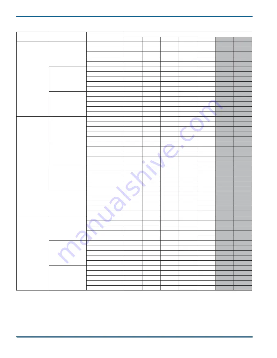
TABLE 11: 

Air Flow Data (CFM)

1

Models

CM Models

Blower 

Motor Speed

External Static Pressure (in. wc.)

0.10

0.20

0.30

0.40

0.50

0.60

0.70

ME08B

CM18B

#5 HI

939

893

871

837

804

767

714

#4 MED-HI

833

803

765

737

697

639

587

#3 MED

638

605

576

494

454

380

278

#2 MED-LO

538

489

456

374

283

211

157

#1 LO

478

446

367

272

211

150

23

CM24B

#5 HI

923

892

862

833

797

743

688

#4 MED-HI

846

816

786

750

710

638

599

#3 MED

631

605

575

512

442

370

282

#2 MED-LO

570

530

460

402

328

232

186

#1 LO

477

448

372

292

203

157

24

CM30B

#5 HI

937

905

877

841

798

748

704

#4 MED-HI

846

808

778

733

667

636

572

#3 MED

638

609

556

495

463

399

336

#2 MED-LO

560

484

469

408

321

265

201

#1 LO

481

448

390

328

252

166

92

ME12B

CM18B

#5 HI

1355

1334

1302

1270

1231

1201

1170

#4 MED-HI

1273

1244

1213

1177

1142

1109

1073

#3 MED

1074

1041

1009

974

936

894

809

#2 MED-LO

862

826

798

766

688

607

587

#1 LO

659

616

560

512

457

387

275

CM24B

#5 HI

1359

1331

1301

1269

1234

1202

1171

#4 MED-HI

1272

1245

1209

1174

1143

1106

1073

#3 MED

1072

1040

1007

973

937

874

778

#2 MED-LO

857

821

794

756

676

613

567

#1 LO

654

606

557

504

443

379

271

CM30B

#5 HI

1354

1325

1294

1263

1230

1198

1168

#4 MED-HI

1268

1235

1203

1171

1139

1107

1075

#3 MED

1069

1038

1003

974

935

876

781

#2 MED-LO

859

818

794

756

681

620

563

#1 LO

654

608

552

503

434

364

289

CM36B

#5 HI

1348

1317

1285

1254

1222

1189

1157

#4 MED-HI

1258

1225

1192

1160

1126

1093

1063

#3 MED

1062

1029

993

964

929

879

778

#2 MED-LO

860

822

791

761

682

616

568

#1 LO

642

599

554

502

431

367

294

ME14D

CM30D

#5 HI

1583

1546

1516

1477

1435

1401

1364

#4 MED-HI

1499

1456

1426

1393

1349

1306

1267

#3 MED

1295

1247

1217

1181

1135

1080

1005

#2 MED-LO

1099

1075

1026

983

909

840

786

#1 LO

906

875

834

754

675

589

521

CM36D

#5 HI

1604

1563

1524

1479

1450

1410

1374

#4 MED-HI

1508

1464

1428

1384

1350

1308

1271

#3 MED

1300

1250

1209

1175

1132

1075

1006

#2 MED-LO

1102

1058

1028

986

909

838

784

#1 LO

912

884

831

763

694

568

530

CM42D

#5 HI

1544

1520

1482

1440

1411

1367

1321

#4 MED-HI

1455

1426

1393

1349

1305

1272

1207

#3 MED

1263

1238

1197

1157

1100

1033

980

#2 MED-LO

1074

1037

993

946

877

810

729

#1 LO

888

853

787

736

644

571

508

For notes, see Page 13

Summary of Contents for ME08B

Page 1: ...ld installed accessories Single phase kits are available from 2 5 kW to 25 kW 208 230 volt three phase kits are available from 10kW to 25kW SECTION II SAFETY This is a safety alert symbol When you see...

Page 2: ...carrier s freight bill A separate request for inspection by the carrier s agent should be made in writing Also before installation the unit should be checked for screws or bolts which may have loosen...

Page 3: ...URATION These air handler units are supplied ready to be installed in an upflow downflow horizontal right or horizontal left position Refer to Figure 2 The unit requires no conversion procedures AIR H...

Page 4: ...ENSIONS C D 12 3 16 19 1 8 B 20 1 2 21 1 2 TABLE 1 Dimensions ME MODELS Dimensions1 Wiring Knockout Dimensions1 2 A B C D E F Height Width Bottom Opening Top Opening Power Control ME08B 21 1 2 17 1 2...

Page 5: ...d be designed in accordance with the Air Conditioning Contractors of America ACCA Manual D HORIZONTAL SUSPENSION For suspension of these units in horizontal applications it is recom mended to use angl...

Page 6: ...for Horizontal right hand airflow applica tion only Follow instructions with heater for modification SECTION VI LINE POWER CONNECTIONS Power may be brought into the unit through the supply air end of...

Page 7: ...heat kit connected to tap 5 for the heating speed and the cooling heat pump connected to tap 4 for the heating speed The cooling heat pump indicating speed is supplied by the thermostat G signal The...

Page 8: ...correct wire sizing TABLE 4 Electrical Heat Minimum Fan Speed Heater Kit Models1 2 3 Nom kW 240V Air Handler Models ME08B ME12B ME14D ME16C ME20D 6HK 0 1 6500206 2 4kW Med Lo 2 Med Lo 2 Med Lo 2 Med L...

Page 9: ...onnect OR 1 with service disconnect 2 1 2 1 with service disconnect no breaker jumper bar OR 2 with service disconnect breaker jumper bar 3 6HK3 3 Phase with terminal block connectors only 6HK4 3 Phas...

Page 10: ...Field Wiring Min Circuit Ampacity MOP 3 208V 230V 208V 230V TABLE 8 Electrical Data For Multi source Power Supply 208 230 1 60 Air Handler Models Heater Models Heater Amps 240V Min Circuit Ampacity M...

Page 11: ...A and MOP requirements are given here only for reference if used with field installed single point power modification S1 32436041000 3 MOP Maximum Overcurrent Protection device must be HACR type circu...

Page 12: ...MED HI 1272 1245 1209 1174 1143 1106 1073 3 MED 1072 1040 1007 973 937 874 778 2 MED LO 857 821 794 756 676 613 567 1 LO 654 606 557 504 443 379 271 CM30B 5 HI 1354 1325 1294 1263 1230 1198 1168 4 ME...

Page 13: ...52 1706 1680 1633 1591 1546 1511 2 MED LO 1545 1505 1468 1432 1393 1351 1307 1 LO 1340 1296 1260 1219 1169 1118 1055 CM48D 5 HI 2062 2024 1993 1952 1910 1868 1836 4 MED HI 2006 1958 1932 1890 1850 181...

Page 14: ...e fan only to assure a dry coil Drill 2 holes one 12 away from the air handler in the supply air duct and on 12 away from the air handler in the return air duct before any elbows in the duct work Inse...

Page 15: ...L AND NATIONAL CODES MUST BE FOLLOWED SEE INSTALLATION INSTRUCTIONS FOR PROPER LOW VOLTAGE FIELD WIRING CONNECTIONS LEGEND LS LIMIT SWITCH SEQ SEQUENCER HE HEATING ELEMENT FL FUSIBLE LINK H SEQUENCER...

Page 16: ...UE BLUE BLUE BLUE YELLOW YELLOW BLACK BLACK YELLOW YELLOW BLACK BLACK RED WHITE BLACK BLUE BLACK BLUE YELLOW BLACK YELLOW YELLOW BLUE BLACK BLUE BLACK YELLOW RLY 1 RLY 2 RLY 3 RLY 6 RLY 5 RLY 4 HE2 FL...

Page 17: ...dry bulb temperature Return air dry bulb temperature Temperature drop 1 2 3 4 5 Low Medium Low Medium Medium High High A B C D Outside air dry bulb temperature Return air wet bulb temperature Supply a...

Page 18: ...oting and correcting any problems Operate the unit through cooling cycles from the thermostat noting and correcting any problems Operate the unit through mechanical heating cycles from the thermostat...

Reviews: