1083292-UIM-A-0114
Johnson Controls Unitary Products
13
CONTROL WIRING
This furnace can be connected to the wall thermostat and outdoor A/C
or heat pump using either conventional low voltage (24 VAC) thermo-
stat wiring OR using four-wire digital communications wiring. To use
conventional low voltage wiring, see the section below entitled “Con-
ventional Low Voltage Control Wiring”. To use four-wire communica-
tions control wiring, see the section below entitled “Control Wiring using
Communicating Controls”.
The Communicating System consists of several intelligent communicat-
ing components including the Communicating Thermostat Control
(touch-screen wall thermostat), modulating variable speed furnace, air
conditioner (15 and 18 SEER premium air conditioners) or heat pump
(15 and 18 SEER premium heat pumps), which continually communi-
cate with each other via a four-wire connection called the A-R-C-B.
Commands, operating conditions, and other data are passed continu-
ally between components over the A-R-C-B. See Figure 18. The result
is a new level of comfort, versatility, and simplicity.
In order to use this furnace in full communications (COMM) mode, it
MUST be installed with the matching touch-screen Communicating
Control (wall thermostat) and an outdoor air conditioner or heat pump
with a fully communicating control.
This furnace may also be used along with the Communicating Thermo-
stat Control and a non-communicating outdoor air conditioner through
the addition of a communicating Outdoor Aux Control board to the out-
door unit. This system allows full communication between the furnace
and thermostat and limited communication to the outdoor unit. See Fig-
ure 19.
This furnace may also be used along with the Communicating Thermo-
stat Control and a non-communicating outdoor air conditioner or heat
pump using COMM between the furnace and thermostat and conven-
tional 24V wiring to the outdoor unit. This system allows full communi-
cation between the furnace and thermostat but no digital
communication with the outdoor unit.
CONTROL WIRING USING COMMUNICATING
CONTROLS
Use the wiring diagram below to connect the furnace control, Communi-
cating Control (wall thermostat) and communicating outdoor unit. Be
sure that all of the “A” terminals are connected together, all of the “B”
terminals are connected together, all of the “GND” or “C” terminals are
connected together and all of the “R” terminals are connected together.
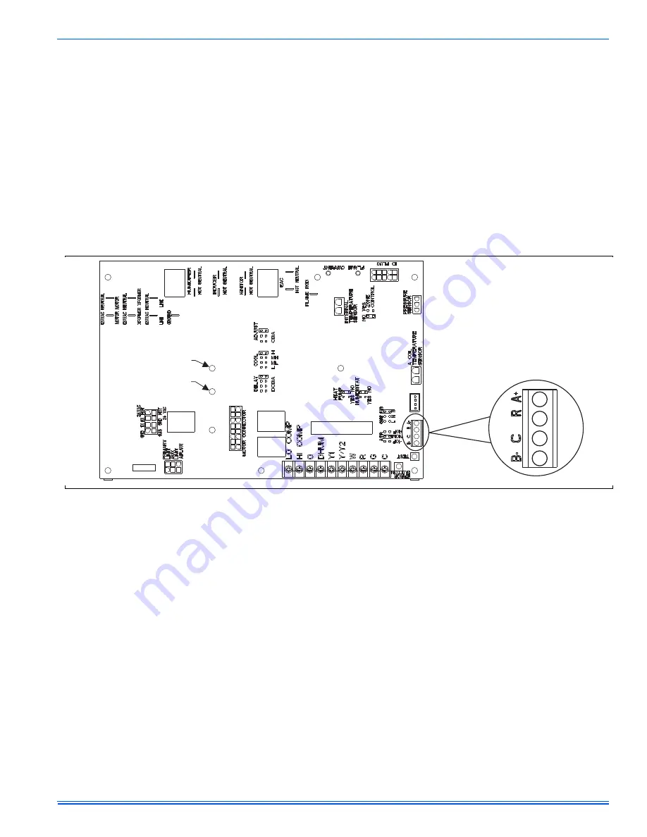
See Figure 19. When using a fully communicating system, the large
screw terminals (C, G, R, etc.) on the furnace control are not used. The
four small screw terminals in the terminal block on the end of the fur-
nace control should be used.
FIGURE 18:
Furnace Control Board – Communications Connections
Diagnostic Light
CFM Light


