


WARNING: Once the correct gas pressure to the
burners has been established, turn the gas valve knob
to OFF and turn the electrical supply switch to OFF;
then remove the pressure tap at the gas valve and
re-install the plug, using a compound (on the threads)
resistant to the action of LP gases. Replace the burner
box front cover or the pressure reference hose.
Turn the electrical and gas supplies back on, and with the
burners in operation, check for gas leakage around the plug
with a soap and water solution.
WARNING: Be sure that gas valve regulator cap and
burner box to gas valve pressure reference hose is
reconnected.
ADJUSTMENT OF TEMPERATURE RISE
The temperature rise, or temperature difference between the
return air and the heated air from the furnace, must be within
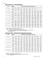
the range shown on the furnace rating plate. Application limita-
tions are shown in Table 1 or 2. After the temperature rise has
been determined, the cfm can be calculated.
After about 20 minutes of operation, determine the furnace
temperature rise. Take readings of both the return air and the
heated air in the ducts, about six feet from the furnace where
they will not be affected by radiant heat.
Increase the blower speed to decrease the temperature rise;
decrease the blower speed to increase the rise.
All direct-drive blowers have multi-speed motors. The blower
motor speed taps are located in the control box in the blower
compartment. Refer to Figure 35 and the unit wiring label to
change the blower speed.
You may select a heating speed and a cooling speed. They may
be the same speed or a different speed.
To use the same speed tap for heating and cooling, the "heat"
terminal and "cool" terminal must be connected using a jumper
wire and connected to the desired motor lead. Place all unused
motor leads on "Park" terminals. Two "Park" terminals are
provided.
CAUTION: Do not energize more than one motor
speed at a time or damage to the motor will result.
ADJUSTMENT OF FAN-OFF CONTROL SETTINGS
This furnace is equipped with a time-on / time-off heating fan
control. The fan "on" is fixed at 30 seconds. The fan "off" is field
adjustable from 60 to 180 seconds. The fan "off" is factory set
to 60 seconds. Adjust the "off" time by repositioning the fan off
switches as located in Figure 35.
The fan-off setting must be long enough to adequately cool the
furnace, but not so long that cold air is blown into the heated space.
The fan-off timing may be adjusted by setting the option switches
located (refer to Figure 35) on the control board as follows:
For units using a Texas Instruments control, connect the jumper
at the desired off timing. Refer to Figure 35 (60 second off timing
shown).
ACCESSORY CONNECTIONS
CAUTION: Do not exceed 1.0 amp loading.
The furnace control will allow power switching control of various
accessories. See Figure 36 for connection details.
Electronic Air Cleaner Connection
Two 1/4" spade terminals (EAC and EAC N) for electronic air
cleaner connections are located on the control board. The
terminals provide 120 VAC (1.0 amp maximum) during circu-
lating blower operation.
HUM
EAC
EAC
HUM
115 VOLT
ELECTRONIC
AIR CLEANER
EAC HOT
HUM HOT
BLK
BLK
WHI
WHI
115 VOLT
HUMIDIFIER
SWITCHED
CIRCUITS
NEUTRALS
FIGURE 36 - ACCESSORY CONNECTIONS
C O O L
H E A T
P A R K
X M
B L K - H I G H S P E E D
B L U - M E D I U M S P E E D
R E D - L O W S P E E D
B L K
B L U
R E D
M O T O R L E A D S
F A N O F F
A D J U S T M E N T
L I N E
P A R K
6 0
90
120
1 8 0
O N
O F F
1
2
W H I T E - R O D G E R S
T E X A S I N S T R U M E N T S
FIGURE 35 - TYPICAL HEAT/COOL SPEED TAP
CONNECTIONS
WHITE-RODGERS CONTROL ONLY
To Delay Fan-Off By:
Set Switch
1 2
60 Sec.
ON
ON
90 Sec.
OFF
ON
120 Sec.
ON
OFF
180 Sec.
OFF
OFF
650.75-N4U
Unitary Products Group
23


