background image

Mechanical Installation

Part 2

Step 6


Parts Required: 

Left Motor Assembly

Left Side Rail

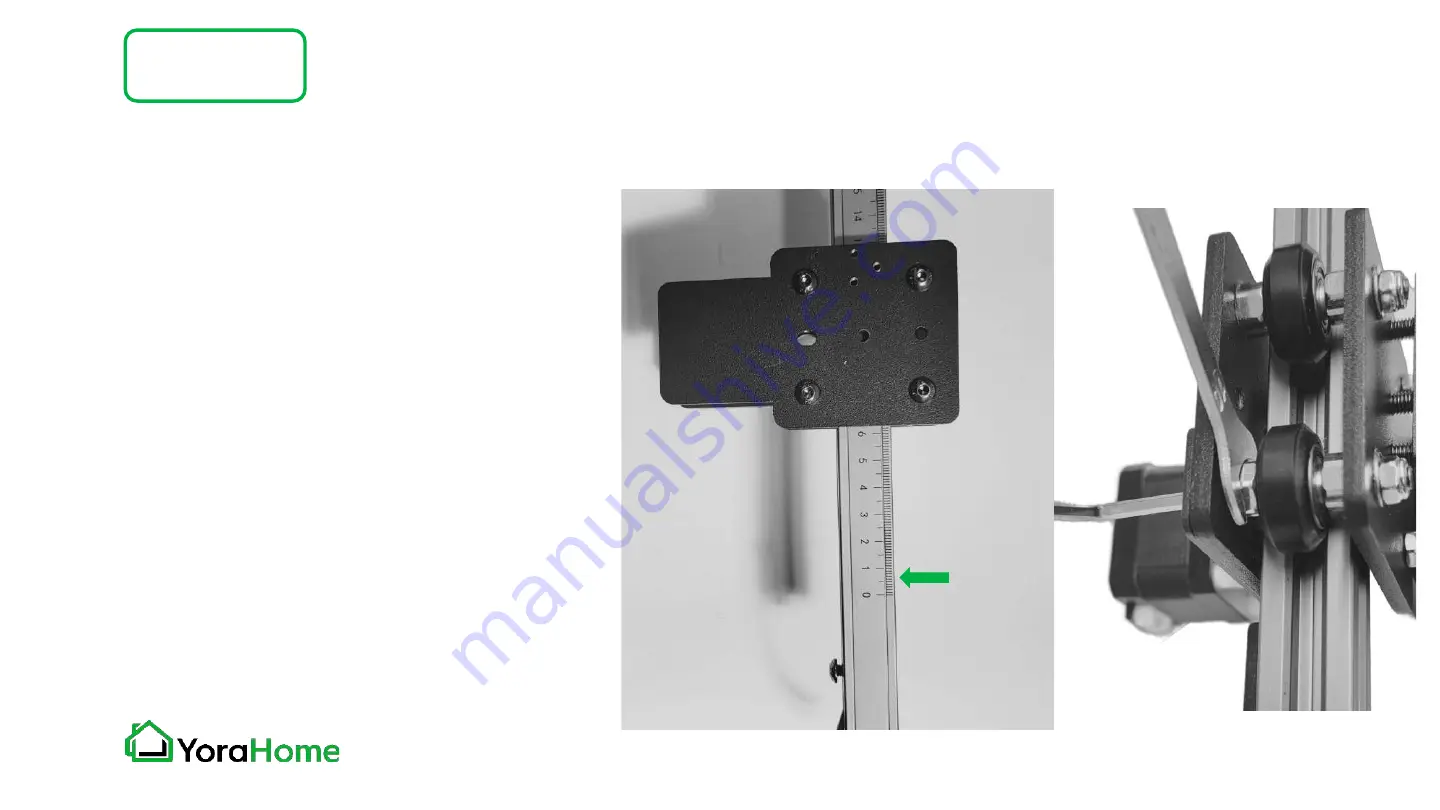
Slide the Left Motor Assembly onto 
the Left Side Rail as shown - note 
the orientation of the measurement 
markings towards the inside of the 
machine frame.

If the assembly is loose, use the 
supplied wrench and hex key to 
adjust the inner rollers as shown.


Roller Adjustment Detail

Measurement 
Markings

Summary of Contents for 6550-PRO

Page 1: ...YORAHOME CNC LASER ENGRAVING MACHINE 6550 PRO USER MANUAL Version 1 0 June 2022...

Page 2: ...assembly we recommend conducting an inventory using the Packing List to ensure all components are present NOTE there may be extra hardware included this is normal in case items get dropped or lost Ple...

Page 3: ...le using the laser engraving machine Everyday eyeglasses will NOT protect your eyes from the laser It is not recommended to wear loose clothing around moving equipment Confine long hair Do not operate...

Page 4: ...t working area with good ventilation Keep children away from your laser engraver Minors of any age should not use this laser without direct adult supervision and proper eye protection Do not place you...

Page 5: ...als please paint the surface black to prevent damage to the laser head from reflective light The machine should be placed securely on a flat surface to avoid dropping or being hit Be within reach of t...

Page 6: ...Contents Part 1 Packing List Part 2 Mechanical Installation Part 3 Software Introduction Part 4 FAQ...

Page 7: ...t 1 Name Model Parameter Quantity Picture Aluminium Profile Front Frame Rail 1 Rear Frame Rail 1 Left Frame Rail 1 Right Frame Rail 1 X Axis Gantry Rail with wiring 1 Bolt M3x6 18 M3x8 8 M5x8 7 M5x18...

Page 8: ...Quantity Picture Timing Belt Y Axis 2 Timing Belt X Axis Brass grommets pre installed 1 Timing Belt Clamp Screw Y Axis 4 Limit Switch Y Axis 1 Wrench For roller adjustment 8mm 10mm 1 Cable Ties 20 Sa...

Page 9: ...8 Part 1 Name Model Parameter Quantity Picture Z Axis Assembly 1 Laser Module Diode 80W Electrical Power 10W Optical Power 1 X Axis Belt Tensioner 1 Laser Height Gauge With Holder 1 Safety Glasses Sty...

Page 10: ...t 1 Name Model Parameter Quantity Picture Frame Foot For rear and left front 3 Frame Foot For right front With flange 1 Hex Wrench 1 5 2 2 5 3 4 1 of each Right Motor Assembly For both X and Y axis 2...

Page 11: ...Packing List5 8 Part 1 Name Model Parameter Quantity Picture Left Motor Assembly For Y axis 1 motor installed 1 X Gantry Assembly Flame detector and limit switch installed 1...

Page 12: ...List6 8 Part 1 Name Model Parameter Quantity Picture Limit Switch Touch Plate 1 Drag Chain Bracket X Axis Stepped design 1 Drag Chain Bracket X Y Axis L shaped design 1 Drag Chain Support Bracket For...

Page 13: ...Packing List7 8 Part 1 Name Model Parameter Quantity Picture USB Cable 1 Control Board Includes wiring air assist tubing and Drag Chain pre attached 1 Power Supply Includes power cord 1...

Page 14: ...Packing List8 8 Part 1 Name Model Parameter Quantity Picture Drag Chain Support Rail 1 Air Pump 1 Air Pump Power Supply 1 Leg extension kit Includes 8 Leg segments 50mm each 4 Leg pads 4 T slot nuts 1...

Page 15: ...Optional Accessories Not Included Part 1 YoraHome Rotate Module YoraHome TLC Rotary Attachment YoraHome 4th Axis YoraHome Honeycomb Platform...

Page 16: ...ts Required 2 M3x6 Screws 2 M5x8 Screws Right Motor Assembly Drag Chain Bracket X Y Axis Drag Chain Support Bracket Using M3x6 Screws attach Drag Chain Bracket X Y Axis to the Right Motor Assembly as...

Page 17: ...hanical Installation Part 2 Step 12 2 Using M5x8 Screws LOOSELY attach Drag Chain Support Bracket to the underside of the Right Motor Assembly as shown Do not tighten these screws until later in assem...

Page 18: ...t markings along the inside edge of the rail On the outside edge of the Left and Right Side Rails check for the clearance bore to allow for screw installation as shown Side Rail measurement markings 0...

Page 19: ...e the Right Motor Assembly onto the Right Side Rail as shown note the orientation of the measurement markings towards the inside of the machine frame If the assembly is loose use the supplied wrench a...

Page 20: ...t Clamp Screws Route Timing Belt with teeth down OVER the synchronous wheel on the Y axis stepper motor and UNDER the rollers as shown Secure belt at both ends of the rail as shown do not overtighten...

Page 21: ...Rail Assembly Limit Switch M5x20 Screw Install the Limit Switch on the underside of the Right Side Rail assembly as shown Limit Switch will be positioned at the right front corner of the machine fram...

Page 22: ...e the Left Motor Assembly onto the Left Side Rail as shown note the orientation of the measurement markings towards the inside of the machine frame If the assembly is loose use the supplied wrench and...

Page 23: ...t with teeth down OVER the synchronous wheel on the Y axis stepper motor and UNDER the rollers as shown Secure belt at both ends of the rail as shown do not overtighten and twist belt Belt should be t...

Page 24: ...nstallation Part 2 Step 81 2 Parts Required 7 M3x6 Screws X Gantry Assembly Z Axis Assembly Drag Chain Bracket X Axis Using 3 of the M3x6 Screws attach Drag Chain Bracket X Axis to the X Gantry Assemb...

Page 25: ...Mechanical Installation Part 2 Step 82 2 Using 4 of the M3x6 Screws attach the Z Axis Assembly to the X Gantry Assembly as shown...

Page 26: ...mbly onto the X Axis Gantry Rail as shown note the orientation of the wiring to avoid pinching wires in the rollers NOTE The 6 pin wire connector end of the rail needs to be oriented to the left of th...

Page 27: ...Frame Rails 4 M5x20 Screws Assemble Frame as shown using M5x20 Screws from the OUTSIDE of the Right and Left Side Rails into the ENDS of the Front and Rear Frame Rails Ensure all measurement markings...

Page 28: ...rame Feet 4 M5x8 Screws 4 M5x20 Screws Assemble Frame Feet to Frame Assembly as shown using M5x8 Screws in the ENDS Right and Left Side Rails and M5x20 Screws into the holes located in the Front and R...

Page 29: ...Mechanical Installation Part 2 Progress Check Your assembly should now look like this if it does not verify the previous assembly steps...

Page 30: ...Assembly from Step 9 5 M5x18 Screws With the Z Axis Assembly facing the front of the machine place the X Axis Gantry Rail Assembly on top of the Right and Left Motor Assemblies Attach with 3 M5x18 Sc...

Page 31: ...rn the machine upside down Insert 1 M5x18 Screw from the underside of the Left Motor Assembly securing the X Axis Gantry Assembly Plug the 6 Pin connector into the stepper motor on the Left Motor Asse...

Page 32: ...Limit Switch Touch Plate 1 M5x25 Screw Install the Limit Switch Touch Plate onto the X Axis Gantry Rail using the center hole on the Left Motor Assembly as shown The vertical part of the Limit Switch...

Page 33: ...ews for the X Axis Belt Tensioner are pre installed Loosen the mounting screws slightly and insert the Belt Tensioner on the left end of the X Axis Gantry Rail The Belt Tensioner will fit against the...

Page 34: ...ed Timing Belt X Axis Starting at the right side of the X Axis Gantry Slide one end of the Timing Belt into the slot on the X Axis Gantry Route the Timing Belt to the X Axis motor on the Right Motor A...

Page 35: ...Axis Gantry Rail and through the Belt Tensioner the belt must go on the inside of the Belt Tensioner housing as shown Slide the other end of the Timing Belt into the slot on the left side of the X Ax...

Page 36: ...Drag Chain Support Rail on the rear side of the X Axis Rail with the flat side of the support rail facing up Using 3 M3x6 Screws attach the Drag Chain Support Rail to the Left Motor Assembly as shown...

Page 37: ...Chain 2 M5x20 Screws Place the Control Board in the right front corner of the machine frame Route the wiring behind the right front foot ensuring that the wiring is not pinched in between the Control...

Page 38: ...g the right side of the machine Ensure the Drag Chain is routed OVER the roller on the Drag Chain Support Bracket on the underside of the Right Side Motor Assembly At this time you may tighten the scr...

Page 39: ...chanical Installation Part 2 Step 20 Parts Required 3 M3x6 Screws Using 3 M3x6 Screws attach the Y Axis Drag Chain to the right front Frame Foot as shown Ensure that no wiring is caught under the scre...

Page 40: ...M3x6 Screws 3 M3x8 Screws Using 3 M3x6 Screws attach the Y Axis Drag Chain to the Right Motor Assembly as shown Using 3 M3x8 Screws attach the X Axis Drag Chain to the Right Motor Assembly as shown En...

Page 41: ...Mechanical Installation Part 2 Step 22 Parts Required 3 M3x6 Screws Using 3 M3x6 Screws attach the X Axis Drag Chain to the X Axis Gantry Assembly as shown...

Page 42: ...ation Part 2 Step 231 6 Wire Connections At the Right Motor Assembly connect the Y Axis Motor harness which is underneath the X Axis Rail Ensure that the wire is routed away from any rollers using cab...

Page 43: ...llation Part 2 Step 232 6 Wire Connections At the Right Motor Assembly connect the X Axis Motor upper motor and Y Axis Motor lower motor Ensure that the wire is routed away from any rollers using cabl...

Page 44: ...ION The 6550 Pro is equipped with a flame detection sensor which will stop the machine in the event of fire detected in the engraving area directly beneath the laser In some circumstances such as dire...

Page 45: ...ical Installation Part 2 Step 234 6 Wire Connections At the rear of the X Axis Gantry connect the X Axis Limit Switch harness Ensure that the wire is routed away from any rollers using cable ties as n...

Page 46: ...llation Part 2 Step 235 6 Wire Connections At the right front corner connect the Y Axis Limit Switch which is underneath the Y Axis Rail Ensure that the wire is routed away from any rollers using cabl...

Page 47: ...stepper motor cable for your rotary can be plugged in to the provided 4 pin connector To activate the rotary connection use the Rotary switch on the back of the controller Switching to the rotary wil...

Page 48: ...Mechanical Installation Part 2 Step 24 Parts Required Laser Module Assembly 4 M3x8 Screws Using 4 M3x8 Screws attach the Laser Module to the Z Axis as shown...

Page 49: ...Connect the Laser Module wire harness to the top of the laser module Connect the Air Assist Tubing to the fitting on the bottom left of the laser module this connection simply pushes in place Laser M...

Page 50: ...Mechanical Installation Part 2 Step 26 Parts Required Laser Height Gauge Holder 2 M5x20 Screws Using 2 M5x20 Screws attach the Laser Height Gauge Holder to the front left corner of the frame as shown...

Page 51: ...wer Supply Attach the small length of tubing with the adapter fitting to the outlet of the Air Pump Connect the Air Assist tubing from the front right corner of the machine to the outlet port of the A...

Page 52: ...ower for 24VDC power supply Connect USB to computer Memory Card not used at this time Power Switch turn machine on off Estop Emergency Stop latches in safe position Warning indicates flame detection h...

Page 53: ...the provided Laser Height Guide adjust the height of the laser using the Z Axis thumbscrew setting the distance between the work surface and the bottom of the laser housing The magnetic shield must be...

Page 54: ...rts Required 8 Leg segments 50mm each 4 T slot nuts 4 Leg pads Using the T slot nuts attach one leg segment 50mm to each corner of the frame to raise the machine You can insert the second leg segment...

Page 55: ...R Download it online here NOTE FOR MAC USERS If your Mac is running Mojave OS or higher do NOT install the driver as the OS has native support for the CH340 If you are running Sierra or High Sierra pl...

Page 56: ...ype Device Manager then select it from the menu In the tree expand Ports COM LPT Your machine will be identified by the USB Serial Port COMX where the X represents the COM number for example COM3 If t...

Page 57: ...lso go to the LaserGrbl official website to download the latest version You will also find on the website many tutorials showing show how to use this powerful software If you own a Mac computer we rec...

Page 58: ...Software Introduction LaserGRBL Part 3 1 2 Open the LaserGRBL Software Select the desired COM port then click the Connect icon...

Page 59: ...below in the Console window Test your machine for proper motion control using the Jog buttons if the Y axis is reversed switch the motor cable to the other white port on the control board The highligh...

Page 60: ...on LaserGRBL Part 3 6 To load an image for engraving click on the File menu then select Open File In the Windows Explorer window navigate to the desired image file on your computer Common file types a...

Page 61: ...ion LaserGRBL Part 3 You can use the default settings or adjust them see our tutorial videos in YoraHome Facebook CNC Users Group or My YoraHome Knowledge Base for additional information 7 Parameters...

Page 62: ...speed and MIN MAX settings will need to be adjusted to meet the material being engraved Note that the size values will automatically update whenever one is changed in order to maintain the aspect rati...

Page 63: ...aserGRBL Part 3 Using the jog buttons position the laser to the lower left corner of the desired burn location then click the Globe button to set the origin Then click the Play button to start the las...

Page 64: ...Software Introduction Lightburn Part 3 1 2 Open the Lightburn Software In the lower right of the screen in the Laser pane click on Devices...

Page 65: ...Software Introduction Lightburn Part 3 3 4 In the Devices dialog box click on the Create Manually button The New Device Wizard will start select the GRBL option and click Next...

Page 66: ...troduction Lightburn Part 3 5 6 The default connection method should be Serial USB click Next If you would like to name the machine you may do so here Set the work area dimensions as shown X 650 Y 500...

Page 67: ...rn Part 3 7 8 Set the origin for your laser on the 6550 that is the Front Left If you wish to use the Auto homing function set that toggle to True click Next Confirm your settings then click Finish to...

Page 68: ...Software Introduction Lightburn Part 3 9 Click on OK to return to the main Lightburn screen...

Page 69: ...oduction Lightburn Part 3 10 Click on the File menu then select Import to open an image file In the Windows Explorer window navigate to the desired image file on your computer Common file types are JP...

Page 70: ...Software Introduction Lightburn Part 3 11 To set the engraving parameters select the image on the grid then go to the Cuts Layers tab in the upper right pane see next page for detail...

Page 71: ...r imported image then select the parameters for your engraving in the example below we have selected a engraving speed of 1000 mm min at a power of 60 with the mode set to Fill This will direct the ma...

Page 72: ...oduction Lightburn Part 3 13 Select the Move tab and use the jog buttons to position your laser at the lower left corner of where the design is to be burned Click on the Set Origin button to set the s...

Page 73: ...e Fire button to turn the laser on at low power for focusing click again to turn the laser off If the Fire button is not visible go to the Device Settings on the Edit menu and select the Enable Laser...

Page 74: ...Software Introduction Lightburn Part 3 15 Finally click on the Start button in the Laser pane to start the laser engraving process...

Page 75: ...Q How tight should my timing belts be on the 6550 Pro A Timing belts should be tight enough to not slip but not so tight as to make smooth movement an operation s issue Q What speed and max power do...

Page 76: ...WWW YORAHOME COM SUPPORT YORAHOME COM...

Reviews: