


<3. Parameter Setting>
3-15
IM 01C50T03-02EN
[Adjustment method]
Set the sensors before input adjustment. (→ 3.2.2
Sensor Setup)
Use the following parameters for adjustment
purposes.
Sensor1
parameter
Sensor2
parameter
Usage
I11:SENSOR1 I21:SENSOR2 Output value. Check
the output value before
and after adjustment.
I12:S1 ZERO
ADJ
I22:S2 ZERO
ADJ
Zero adjustment value.
Set the target value of
the zero adjustment
point.
I13:S1 SPAN
ADJ
I23:S2 SPAN
ADJ
Span adjustment value.
Set the target value of
span adjustment point.
I14:S1 ZERO
DEV
I24:S2 ZERO
DEV
Zero adjustment
amount. The difference
between the zero
adjustment point
target value and the
unadjusted output
value is displayed.
I15:S1 SPAN
DEV
I25:S2 SPAN
DEV
Span adjustment
amount. The difference
between the span
adjustment point
target value and the
unadjusted output
value is displayed.
I16:S1 ADJ
CLR
I26:S2 ADJ
CLR
When “EXEC” is
written, the user
adjustment is
reset to the default
characteristics.
The following explains the Sensor1 input
adjustment. For input adjustment of Sensor2, read
the parameters based on the above table.
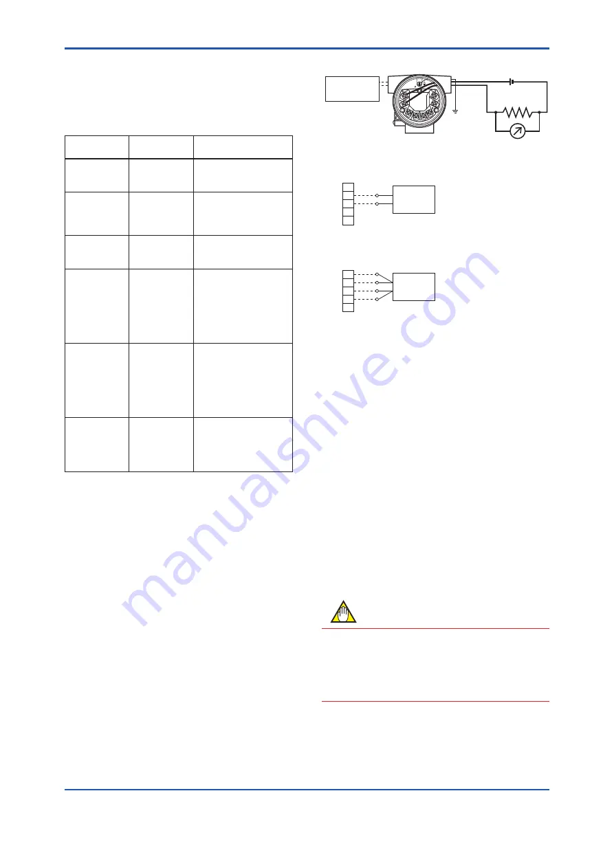
(1) Connect the calibration equipment to the
temperature transmitter in an stable ambient
temperature environment, and warm up for
three or more minutes. (See Figure 3.5. For
Sensor2 adjustment, check wiring methods (b)
and (c) of Section 5.4 “Connecting Cables and
Terminals” of IM 01C50G01-01EN.)
(2) Apply the input, that corresponds to the zero
adjustment value, to Sensor1.
a. Power supply and output wiring
b. Wiring example for thermocouple or DC voltage input
(in case of 1-input model)
F0313.ai
Output signals
-
Load resistance
(250 Ω)
DC voltage generator or
thermocouple
Voltmeter
1
2
3
4
5
c. Wiring example of resistance temperature detector
4-wire type (1-input model)
Variable resistor or resistance
temperature detector
1
2
3
4
5
(+)
(A)
(B)
(B)
(A)
(-)
+
Reference input
generator
Figure 3.5
Wiring example of calibration
equipment
(3) Check the output value of Sensor1 from
“I11:SENSOR1”. (Presence or absence of
difference with expected value for input of (2))
(4) Write the expected value for input of (2) to
“I12:S1 ZERO ADJ”.
Example:
When input corresponding to a temperature
of 0°C is given to Sensor1, write “0” in “I12:S1
ZERO ADJ”.
The 1-point adjustment ends in Step (4). For 2-point
adjustment, perform Steps (5) and (6).
(5) Now, adjust the span. Apply the input, that
corresponds to the span adjustment value, to
Sensor1.
(6) Write the expected value for input of (5) to
“I13:S1 SPAN ADJ”.
NOTE
When “EXEC” is written in the “I16:S1 ADJ CLR”
parameter (or when “EXEC” is written in “I26:S2
ADJ CLR” for Sensor2), the user adjustment is
reset to the default characteristics. After the reset,
this parameter value is returned to “NOEXEC”.


