


<3. Parameter Setting>
3-8
IM 01C50T03-02EN
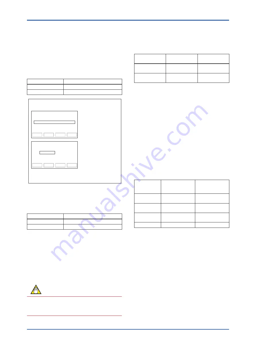
(1) Setting LRV and URV
There are two ways to set the LRV and URV: by
entering LRV and URV numeric values directly, and
by providing real input.
a) Specify LRV and URV directly as numerical
values.
Directly set the LRV and URV using the following
parameters. The unit specified by “B11:PV UNIT” is
used.
Setting target
Setting parameter
LRV
E10:LRV
URV
E11:URV
F0304.ai
DATA
DIAG
PRNT
ESC
PARAM
E10:LRV
0 degC
E11:URV
100 degC
E12:AUTO LRV
NO EXEC
DEL
CLR
ESC
PARAM
E11:URV
0 degC
+ 150
1. Select “E11:URV”, and
press [ENTER].
2. Enter value “150”, and
press [ENTER] twice.
3. Press [OK].
<Setting has completed.>
Note: Units specified in “B11:PV UNIT” are used. If the
unit is changed by B11, the units used in E10 and
E11 are also changed.
●
Example: Change the measurement range from
“0 to 100°C” to “0 to 150°C”.
b) Changing the range by applying an actual input
Enter a value in the transmitter, and set the PV
value in the LRV or URV unit. Use the following
parameters for unit setting.
Setting target
Setting parameter
LRV
E12:AUTO LRV
URV
E13:AUTO URV
The following shows the procedure.
1. Give the input equivalent to LRV to the
transmitter and stabilize it.
2. Select “EXEC” from “E12:AUTO LRV”, and
press the [ENTER] key twice.
3. The value set as LRV is displayed. Confirm it,
and press [OK].
4. Similarly, set the URV using “F13:AUTO URV”.
NOTE
With E12 and E13, after execution by selecting
EXEC, the system returns to the NO EXEC state
automatically.
(2) Setting the calculation output lower limit
and calculation output upper limit
Set the calculation output lower limit and
calculation output upper limit by using the following
parameters.
Setting target
Setting
parameter
Allowable range
Calculation output
lower limit
I40:NRML MIN
OUT
3.6 to 4.0 mA
Calculation output
upper limit
I41:NRML MAX
OUT
20.0 to 21.6 mA
3.2.6 Damping time constant
This function adjusts the response speed against
sudden input fluctuations in terminal block
temperature, Sensor1 and Sensor2 digital outputs,
and 4 to 20 mA analog output. The terminal block
temperature and Sensor1 and Sensor2 damping
settings are also reflected on the PV to QV digital
outputs, which are their mapping destinations.
There are two types of damping setting items:
the damping time constant, and the damping
calculation threshold. Of these, the damping
calculation threshold is set only by damping of
analog output.
The following shows the target of damping setting
and its setting parameters.
Setting target
Damping time
constant
Damping
calculation
Threshold
Terminal block
temperature
B52:TERM DAMP ―
SENSOR1
D14:SENSOR1
DAMP
―
SENSOR2
D34:SENSOR2
DAMP
―
Analog output E20:AO DAMP
E21:AO DAMP PT


