YOKOGAWA WT1801E User Manual Download Page 87

15-3

IM WT18O1E-02EN

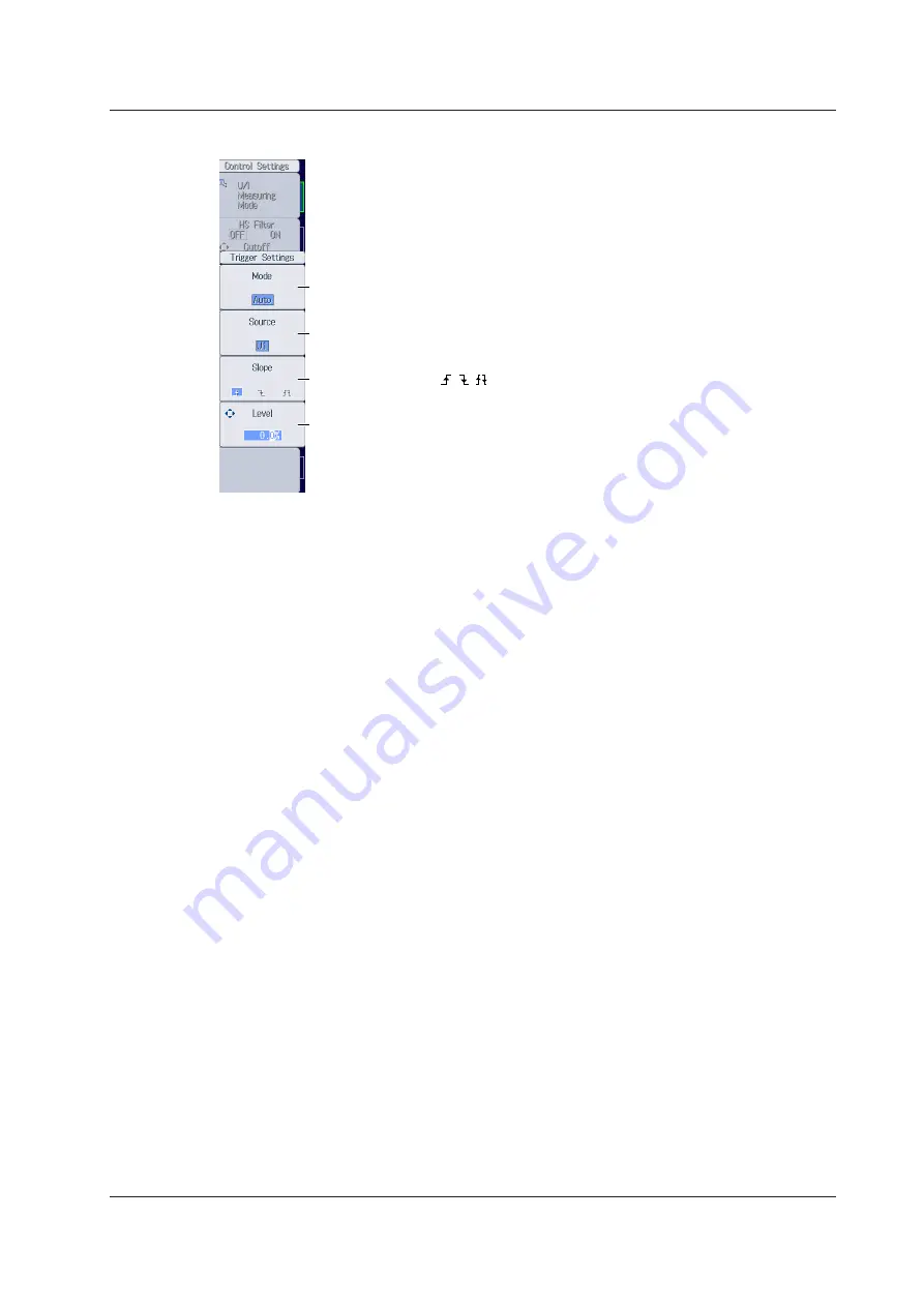
Configuring Trigger Settings


Set the trigger slope (    ,    ,    ). 

Set the trigger mode (Auto, Normal, OFF). 

Set the trigger source (U1, I1, U2, I2, U3, I3, U4, I4, U5, I5, U6, I6, Ext Clk).

Set the trigger level (0.0% to ±100.0%).

15.1  Setting the Number of Data Captures and Configuring the Capture Control Settings

Summary of Contents for WT1801E

Page 1: ...IM WT1801E 02EN 3rd Edition Precision Power Analyzer WT1801E WT1802E WT1803E WT1804E WT1805E WT1806E...

Page 2: ...wer Analyzer Communication Interface User s Manual IM WT1801E 17EN The supplied CD contains the PDF file of this manual This manual explains the communication interface features of this instrument and...

Page 3: ...dobe and Acrobat are either registered trademarks or trademarks of Adobe Systems Incorporated Modbus is a registered trademark of AEG Schneider In this manual the and TM symbols do not accompany their...

Page 4: ...s that can be taken to prevent such occurrences CAUTION Calls attention to actions or conditions that could cause light injury to the user or damage to the instrument or user s data and precautions th...

Page 5: ...s to the appropriate setting F Press the soft key to use the cursor keys to configure this setting After you configure the setting the status of the selected setting switches each time you press the s...

Page 6: ...right cursor keys Changes which digit to set When selecting the item to set Up and down cursor keys Moves the cursor between settings How to Enter Values in Setup Dialog Boxes 1 Use the keys to displa...

Page 7: ...sition you want to insert characters into To switch between uppercase and lowercase letters move the cursor to CAPS on the keyboard and then press SET To delete the previous character press the Back S...

Page 8: ...History A List of Previously Entered Character Strings After selecting an item with the cursor keys press SET to confirm it Enter a preset character string Note cannot be entered consecutively File n...

Page 9: ...ine Filters 1 17 1 14 Setting Frequency Filters 1 18 1 15 Setting the Data Update Interval 1 19 1 16 Setting Averaging 1 20 1 17 Displaying the Menu for Configuring All Elements 1 21 1 18 Displaying t...

Page 10: ...tions to Display and the Vertical Scales 10 3 Chapter 11 Bar Graph Display Option 11 1 Setting the Display Format 11 1 11 2 Setting the Measurement Function to Display and the Vertical Scale 11 2 Chap...

Page 11: ...ring TCP IP Settings 20 3 20 3 Accessing this instrument from a PC FTP Server 20 4 20 4 Monitoring the display of this instrument from a PC Web Server 20 5 20 5 Connecting to a Network Drive 20 8 20 6...

Page 12: ...lement numbers are larger than the selected element On models that have six input elements installed up to three wiring units A B and C are automatically set The wiring unit symbols A B and C are atta...

Page 13: ...elements for which the following conditions are met The input element type for 5 A or for 50 A is the same The valid measurement range setting see section 1 7 is the same 2 Follow the instructions bel...

Page 14: ...rrent range Auto Range Setting Press the current range s AUTO key Setting the Fixed Range Press the current range s fixed range keys and to set the current range Available Current Range Options 5 A In...

Page 15: ...set the current range that is used when current is applied directly to this instrument see section 1 2 3 Follow the instructions below to set the external current sensor range Auto Range Setting Pres...

Page 16: ...on ratio of the input element that is indicated by the cursor is copied to all the input elements in that element s wiring unit Cursor use the cursor keys to move it Note When using the dedicated shun...

Page 17: ...ress SHIFT the ELEMENT ALL key for setting ranges to collectively configure all the input elements for which the following conditions are met The input element type for 5 A or for 50 A is the same The...

Page 18: ...e CT ratio Set the power coefficient When you want to multiply the external current sensor output by the conversion ratio and read the current of the circuit under measurement directly turn the VT CT...

Page 19: ...it Note When using the dedicated CT you can select a CT ratio preset in the menu for configuring all elements see section 1 17 Setting the Power Coefficient SF Scaling Press the SF Scaling soft key to...

Page 20: ...curs When Element Independent is set to OFF the input elements that are assigned to the same wiring unit are set to the same range If auto range is on you can turn it on by pressing AUTO this instrume...

Page 21: ...is displayed in yellow For each input element or wiring unit you can set all ranges as valid measurement ranges All ON Available options for the measurement ranges that this instrument can switch to w...

Page 22: ...easurement ranges whose check boxes have been selected Available current range options Setting the Valid Measurement Range of External Current Sensors Ext Sensor Input Element Valid measurement range...

Page 23: ...tems Set the denominator and numerator of the efficiency equation to the active power and motor power measurement functions P1 to P6 1 P A to P C 2 Pm 3 Udef1 Udef2 You can set up to four equations 1...

Page 24: ...ff This section explains how to turn the independent input element configuration on and off Independent Input Element Configuration Element Independent in the features guide Wiring Menu Press WIRING t...

Page 25: ...omputation Settings Measure Press WIRING and then the Measure soft key to display the following screen The set wiring systems Set the delta computation type The available options vary depending on the...

Page 26: ...st Factor This section explains how to set the crest factor Crest Factor Crest Factor in the features guide System Config Menu Press UTILITY and then the System Config soft key to display the followin...

Page 27: ...interval is Auto Setting the Synchronization Source for When the Data Update Interval is Auto Sync Source Setting Press SYNC SOURCE and then the Sync Src Setting soft key to display the following scr...

Page 28: ...lter Menu Press LINE FILTER to display the following menu Configure the line filter settings Turn the line filter on or off Set the cutoff frequency 0 1kHz to 100 0kHz in steps of 0 1 kHz 300kHz 1MHz...

Page 29: ...enu for when the data update interval is Auto Freq Filter A Menu When the data update interval is Auto Press SHIFT LINE FILTER FREQ FILTER and then the Freq Filter at Update Rate Auto soft key to disp...

Page 30: ...enu Increases the data update interval1 Set the data update interval 50ms 100ms 200ms 500ms 1s 2s 5s 10s 20s Decreases the data update interval1 The current data update interval Set whether to set the...

Page 31: ...Attenuation constant Average count Averaging AVG in the features guide Averaging Menu Press AVG to display the following menu Set the averaging type Exp Lin Turns averaging on and off Set the attenua...

Page 32: ...Elements All Elements Setup in the features guide All Elements Setup Menu 1 Press WIRING and then the All Elements Setup soft key to display the following menu Use the cursor keys to select the settin...

Page 33: ...he INPUT INFO key illuminates and the split display appears The top half of the screen displays the setup parameter list Press INPUT INFO again to clear the setup parameter list and display the previo...

Page 34: ...1 23 IM WT18O1E 02EN Info Items Menu 3 Press ITEM to display the Info Items menu Turns the display frame on and off 1 17 Displaying the Setup Parameter List...

Page 35: ...harmonic order 0 1 Set the maximum value of the measured harmonic order 1 to 500 Set the distortion factor equation 1 Total 1 Fundamental Set the PLL source U1 I1 U2 I2 U3 I3 U4 I4 U5 I5 U6 I6 Ext Clk...

Page 36: ...lement Settings Press the Element Settings soft key to display the following menu Set the group of the input element Hrm1 Hrm2 Input elements that are assigned to the same wiring unit are set to the s...

Page 37: ...1 I1 U2 I2 U3 I3 U4 I4 U5 I5 U6 I6 Ext Clk None Even if Sense Type is set to Pulse correctly setting the synchronization source improves measurement accuracy When Sense Type is set to Pulse Set the up...

Page 38: ...second X axis value V and Y axis value Nm 1 000 T to 1 000 T Computes A and B Cancels the computation Setting the Electrical Angle Correction Value Electrical Angle Correction On the motor evaluation...

Page 39: ...the scaling factor 0 0001 to 99999 9999 Set the unit up to 8 characters Turns the auto range on and off Set the fixed range 20V 10V 5V 2V 1V 500mV 200mV 100mV 50mV Set the linear scale A 1 000 m to 1...

Page 40: ...umeric data that is being printed on the built in printer and communication output are also held Press HOLD again to turn the HOLD key off This releases the hold feature The measured data is then upda...

Page 41: ...performed at the specified data update rate and this instrument then holds the measured value Note If while the HOLD key is illuminated you press HOLD again the HOLD key will turn off and the hold fea...

Page 42: ...nfo Form menu may be displayed If this happens press FORM again Select the 4 Items display Select the All Items display Select the harmonics list display G5 or G6 option This instrument switches betwe...

Page 43: ...ed page separately for the 4 Items 8 Items 16 Items Matrix All Items and Custom displays For the All Items display the first page is always displayed in the top half of the screen and the currently se...

Page 44: ...y the next page Press SHIFT PAGE to jump to the first page Press SHIFT PAGE to jump to the last page The arrows that can be used to switch the page are displayed in black To the previous page To the n...

Page 45: ...list is being displayed the INPUT INFO key is illuminated the Info Items menu may be displayed If this happens press ITEM again In step 1 you can also display the Numeric 4 Numeric 8 or Numeric 16 men...

Page 46: ...ys or the SHIFT PAGE and keys to select the item that you want to change 5 Press the function select key that corresponds to the measurement function that you want to display Function select keys U I...

Page 47: ...parameter list is being displayed the INPUT INFO key is illuminated the Info Items menu may be displayed If this happens press ITEM again In step 1 you can also display the Matrix Items menu by press...

Page 48: ...n Element Origin Function Origin Clear Current Page Clear All Pages Column Settings Menu Press the Column Settings soft key to display the following menu Resets items to the default values Set the num...

Page 49: ...he SHIFT PAGE and keys to select the row that you want to change 5 Press the function select key that corresponds to the measurement function that you want to display Function select keys U I P key S...

Page 50: ...All menu by pressing NUMERIC ITEM and then repeatedly pressing NUMERIC Turns the display of numeric data of all elements or all wiring units on and off If the total number of elements or wiring units...

Page 51: ...ay be displayed If this happens press ITEM again In step 1 you can also display the List Items menu by pressing NUMERIC ITEM and then repeatedly pressing NUMERIC There is a List Items menu for the sin...

Page 52: ...ant to display Function select keys U I P key and S Q key The WP q TIME key FU FI key and U I MODE key are disabled 6 Press the ELEMENT key for displaying numeric data to select the element and wiring...

Page 53: ...Custom Custom Items Menu 2 Press ITEM to display the following menu If the setup parameter list is being displayed the INPUT INFO key is illuminated the Info Items menu may be displayed If this happe...

Page 54: ...ction None other functions for details on the various measurement functions see Items That This Instrument Can Measure in the features guide Set the element and wiring unit Element 1 to Element 6 A to...

Page 55: ...e Load Items Bmp Follow the procedure on page 6 12 to display the Custom Items menu and then press the Load Items Bmp soft key to display the following screen Loads the file Select the file that you w...

Page 56: ...Custom Display Note After you properly load a display configuration file and a background file if you restart this instrument and the same background file is not in the same location the background wi...

Page 57: ...d Functions User Defined Function Press MEASURE and then the User Defined Function soft key to display the following screen Displays the setup screen for user defined functions F1 to F5 Displays the s...

Page 58: ...rform judgment Range Set the measurement function for details on the various measurement functions see Items That This Instrument Can Measure in the features guide Set the element and wiring unit Elem...

Page 59: ...Equations Formula in the features guide Formula Menu Press MEASURE and then the Formula soft key to display the following menu Set the apparent power equation Urms Irms Umean Imean Udc Idc Umean Irms...

Page 60: ...ng Frequency This section explains how to set the sampling frequency Sampling Frequency Sampling Frequency in the features guide Measure Menu Press MEASURE to display the following menu Set the sampli...

Page 61: ...y Format This section explains how to set the phase difference display format Phase Difference Display Format Phase in the features guide Measure Menu Press MEASURE to display the following menu Set t...

Page 62: ...plains the following setting for master and slave synchronized measurement Master and slave Master Slave Synchronized Measurement Sync Measure in the features guide Measure Menu Press MEASURE to displ...

Page 63: ...g the Voltages or Currents Whose Frequencies Will Be Measured This instrument can measure the frequencies of the voltages or currents of all elements so the setup menu is not displayed even if you pre...

Page 64: ...key is displayed when Independent Control is set to ON The input elements that independent integration will be performed on are displayed Turns independent integration on and off Even if you select in...

Page 65: ...ontinuous Turns integration auto calibration on and off1 Set the watt hour integration methods for each polarity 1 Set the current modes for current integration Set the rated time of integrated D A ou...

Page 66: ...ule setup method Each All When you select Each you can set the schedule for each input element Scheduled integration start time Scheduled integration stop time Sets the scheduled integration start tim...

Page 67: ...e setup method Each All When you select Each you can set the current mode for each input element Setting the Rated Time of Integrated D A Output D A Output Rated Time DA option Press the D A Output Ra...

Page 68: ...orce integration to stop press this soft key The integration time and integrated value are held The STOP indicator to the right of the INTEG key blinks Integration has stopped Integ Stop is displayed...

Page 69: ...at Power Failure Recovery Integration Resume Action at Power Failure Recovery Integration Resume Action in the features guide Integration Resume Action Menu Press UTILITY the System Config soft key a...

Page 70: ...visions of the waveform screen Single Dual Triad Quad Hexa 1 Set waveform mapping Set the time axis 0 05 ms to 2 Configure trigger settings 3 Configure the advanced waveform display settings the speci...

Page 71: ...splay Settings menu are also reflected in the advanced trend display settings see section 10 1 Setting Waveform Mapping Wave Mapping Press the Wave Mapping soft key to display the following screen Set...

Page 72: ...lowing menu If the setup parameter list is being displayed the INPUT INFO key is illuminated the Info Form menu may be displayed If this happens press ITEM again Set the vertical position 0 000 to 130...

Page 73: ...you can still show the trend display You can split the screen into top and bottom halves and show the trend display in one half and another display in the other half chapter 13 Trend Form Menu Press F...

Page 74: ...wing menu Turns the display of scale values on and off Set the display interpolation Set the grid Turns the display of trend labels on and off Note Changes that you make to the trend display settings...

Page 75: ...st is being displayed the INPUT INFO key is illuminated the Info Form menu may be displayed If this happens press ITEM again Set the element and wiring unit Element 1 to Element 6 A to C Set the measu...

Page 76: ...l show the bar graph display You can split the screen into top and bottom halves and show the bar graph display in one half and another display in the other half chapter 13 Bar Form Menu Press FORM to...

Page 77: ...ITEM to display the following menu If the setup parameter list is being displayed the INPUT INFO key is illuminated the Info Form menu may be displayed If this happens press ITEM again Select the bar...

Page 78: ...RS to display the following menu Select Vector Even if you select one of these settings you can still show the vector display You can split the screen into top and bottom halves and show the vector di...

Page 79: ...Info Form menu may be displayed If this happens press ITEM again If setup parameter list is being displayed the vector that you have set to vector number 1 is displayed in the bottom half of the scree...

Page 80: ...e bottom half of the screen Numeric Wave Bar Vector This feature is available on models with the G5 or G6 option The split screen that you configure last is displayed Form Menu Press FORM to switch be...

Page 81: ...ector Section 12 2 If the setup parameter list is being displayed the INPUT INFO key is illuminated the setup parameter list is displayed in the top half of the screen and the screen that you set to d...

Page 82: ...orms Wave Cursor Menu 2 Press SHIFT FORM CURSOR to display the following menu Set the cursor movement path Max Min Mid Turns the cursor display on and off Set the waveform to measure with cursor 1 U1...

Page 83: ...t on and off Cursor Measurement in the features guide 1 Follow the procedures in chapter 10 to display trends Trend Cursor Menu 2 Press SHIFT FORM CURSOR to display the following menu Turns the cursor...

Page 84: ...off Cursor position Turning linked cursor movement on and off Cursor Measurement in the features guide 1 Follow the procedures in chapter 11 to display bar graphs Bar Cursor Menu 2 Press SHIFT FORM C...

Page 85: ...ss OTHERS to display the following menu Select High Speed Data Capturing HS Settings Menu Press FORM to display the following menu Set the number of data captures Infinite 1 to 9999 Confirm and optimi...

Page 86: ...to the maximum capturing count displayed to the left Configuring Capture Control Settings Control Settings Press the Control Settings soft key to display the following menu Turn external signal synchr...

Page 87: ...s Set the trigger slope Set the trigger mode Auto Normal OFF Set the trigger source U1 I1 U2 I2 U3 I3 U4 I4 U5 I5 U6 I6 Ext Clk Set the trigger level 0 0 to 100 0 15 1 Setting the Number of Data Captu...

Page 88: ...omment Save Conditions File Settings in the features guide 1 Follow the procedure in section 15 1 to select High Speed Data Capturing on the Others menu File Settings Menu 2 Press FORM and then the Fi...

Page 89: ...ON or not All OFF Slot in which an input element is not installed You can set whether to save all the numeric data All ON or not All OFF For each input element or wiring unit you can set whether to s...

Page 90: ...ection 15 1 to select High Speed Data Capturing on the Others menu HS Items Menu 2 Press ITEM to display the following menu Resets items to the default values Peak over range information Turns the dis...

Page 91: ...models with the MTR option Aux1 and Aux2 are displayed on models with the AUX option Page 4 Example Page 4 can only be selected on models with the MTR or AUX option Speed Torque and Pm are displayed...

Page 92: ...lect the column that you want to change 5 Press the ELEMENT key for displaying numeric data to select the element and wiring unit that you want to display In high speed data capturing the elements and...

Page 93: ...turing HS State Start appears in the upper right of the screen While the captured data is being saved File State Rec appears in the upper left of the screen French ATTENTION Pendant la collecte de don...

Page 94: ...reen When the captured data is being saved File State Rec appears in the upper left of the screen Stops high speed data capturing After the specified number of data captures have been made high speed...

Page 95: ...ptimizing the Maximum Storage Count Press the Optimize Count soft key to display the following screen Maximum storage count 0 to the maximum number of times that data can be stored to the save destina...

Page 96: ...he Real time Control soft key to display the following screen Set the scheduled start and stop times Year month day 00 hours 00 minutes 00 seconds to 23 hours 59 minutes 59 seconds Scheduled storage s...

Page 97: ...e count page 16 1 Select the trigger event Event 1 to Event 8 When measured data is updated storage is started if the conditions of the specified user defined event are met Single Shot Storage Mode Se...

Page 98: ...yed on the screen Stores the numeric data that you have specified on the Store Items setup screen Press this soft key to store the numeric data items that you have specified on the Store Items setup s...

Page 99: ...perform manual CSV conversion Set auto naming section 17 2 Select whether to perform automatic CSV conversion when storage stops Set the file name section 17 2 Set a comment section 17 2 Setting the...

Page 100: ...kage est en cours quand la touche STORE START est clair e ou quand elle clignote ou bien quand la touche STORE STOP clignote Starting the Storage Operation Press STORE START This instrument starts sto...

Page 101: ...stored data to a file and closes the file If the storage operation has automatically stopped When the storage operation stops automatically this instrument finishes writing stored data to a file and...

Page 102: ...d endommager le support de stockage ou les donn es qu il contient Quand le syst me acc de au support de stockage USB s affiche au centre dans la partie sup rieure de l cran et le voyant du support de...

Page 103: ...ss version 1 1 Do not connect an incompatible USB memory device You cannot use protected USB memory devices such as those that contain encrypted content Do not connect and disconnect the two USB devic...

Page 104: ...e Set a comment Set the file name You can set the file name that is used when Auto Naming is set to OFF This is also used as the common file name when Auto Naming is set to Numbering Saves the data Se...

Page 105: ...he exact same date and time down to seconds exists The sequence number that comes after the date and time is appended if a file name with the exact same date and time down to seconds exists The sequen...

Page 106: ...ave destination Auto naming File name Comment Saving Waveform Display Data Save Wave in the features guide Save Wave Menu Press FILE and then the Save Wave soft key to display the following menu Set t...

Page 107: ...t a comment section 17 2 Set the file name section 17 2 Saves the data Setting the Numeric Data Items to Save Item Settings Press the Item Settings soft key to display the following menu Saves the num...

Page 108: ...d Items soft key on the menu on the previous page the numeric data items that you have specified on the following screen are saved Selects all the numeric data items Clears the selection of all the nu...

Page 109: ...then the Load Setup soft key to display the following screen Select the SET file that you want to load Loads the file Note This instrument cannot load setup parameters that have been saved by a produ...

Page 110: ...ys to move the cursor Sorts the file list Set the display format Set the type of file to list Changes the storage medium drive Deletes the selected files and folders Renames files and folders Makes fo...

Page 111: ...ame in descending order Sorts by file size in ascending order Sorts by file size in descending order Sorts by date and time in ascending order Sorts by date and time in descending order Setting the Di...

Page 112: ...splay background files PNG Screen image data files PNG format JPG Screen image data files JPEG format TXT Custom display configuration files Changing the Storage Medium or Drive Change Drive Select Ch...

Page 113: ...t the following operations Files Press SET or the Set Reset soft key on the Utility menu Folders Press the Set Reset soft key on the Utility menu If you press SET all the files and folders that you ha...

Page 114: ...s and folders Copy Executes the copy operation on the selected files and folders Copy Exec Folder that you are copying to File list that you are copying to File list that you are copying from 3 Select...

Page 115: ...ou are moving data from 3 Select the drive or folder in the file list that you are moving to 4 Select Move Exec on the operation menu to display the following screen Confirms the moving of files and f...

Page 116: ...key selects the file or folder in the file list that is highlighted or clears the selection The selection marks see page 17 8 are displayed to the left of the selected files Select All and Clear All A...

Page 117: ...mages in the features guide Image Save Menu Press SHIFT IMAGE SAVE MENU to display the following menu Set the save destination section 17 2 Set the data format BMP PNG JPEG Set the color OFF Color Rev...

Page 118: ...dark place Use the paper as quickly as possible after you break its protective seal If you attach a plastic film that contains plasticizing material such as vinyl chloride film or cellophane tape to...

Page 119: ...ans l ouverture de sortie du papier en rouleau de l imprimante Ne pas laisser une main ou des doigts entrer en contact avec le dispositif de coupe lors de l ouverture du couvercle de l imprimante et d...

Page 120: ...ent until you hear a click Close the cover until you hear a click Tray Cover Stopper Push the stopper to the left to release the latch Cover Push the printer unit until you hear a click This completes...

Page 121: ...he paper up against the top of the cover Note If you open the printer cover immediately after you cut the roll paper repeat steps 5 to 7 on pages 19 2 and 19 3 After you load roll paper and close the...

Page 122: ...al scheduled times for real time printing trigger event synchronized to a user defined event and printing data when printing starts Comment Feeding paper Printing Screen Images and Numeric Data Option...

Page 123: ...unt Infinite 1 to 9999 Set the print interval Select whether to print the data at print start Setting the Print Interval Press the Print Interval soft key to display the following screen Set the print...

Page 124: ...e Sets the scheduled print start time to the current time Copies the scheduled print start time to the scheduled print stop time Integration Synchronized Print Mode Set Print Mode to Integ Sync Set th...

Page 125: ...19 8 IM WT18O1E 02EN 19 2 Printing Using the Built in Printer Option Printing Press Print to print data according to the conditions specified in the Print Menu menu...

Page 126: ...nical specifications IEEE802 3 Transmission system Ethernet 1000BASE T 100BASE TX 10BASE T Communication protocol TCP IP Supported services FTP server DHCP DNS remote control VXI 11 SNTP FTP client Mo...

Page 127: ...ment and the PC 2 Connect one end of a UTP or STP cable to the ETHERNET 1000BASE T port on the rear panel 3 Connect the other end of the UTP or STP cable to a hub or router 4 Connect the PC to the hub...

Page 128: ...wing screen Set the DHCP OFF ON Set these when DHCP is set to OFF IP address Subnet mask Default gateway These are displayed when DNS is set to ON or Auto Domain name DNS server IP address 1 primary 2...

Page 129: ...eb Server Press UTILITY the Network soft key and then the FT WebP Server soft key to display the following menu Set the user name up to 32 characters Set the password up to 32 characters Set the timeo...

Page 130: ...ument from the PC User name Password Connecting to the DLM4000 from a PC Web Server Web Server in the features guide Configuring Web Server Settings FTP Web Server Press UTILITY the Network soft key a...

Page 131: ...s shown on the previous page and connect to this instrument The following screen appears Note If you set the user name to anonymous you can access this instrument without entering a password Home Scre...

Page 132: ...s Screen 5 Click the Link tab The following screen appears Link to Yokogawa Test Measurement power analyzer website Link to Yokogawa Test Measurement website 20 4 Monitoring the display of this instru...

Page 133: ...etwork drive Network Drive Net Drive in the features guide Configuring Network Drive Net Drive Settings and Connecting to It Press UTILITY the Network soft key and then the Net Drive soft key to displ...

Page 134: ...e System Config menu Time adjustment SNTP SNTP in the features guide Configuring SNTP Settings SNTP Press UTILITY the Network soft key and then the SNTP soft key to display the following menu Configur...

Page 135: ...ation List System Overview Press UTILITY and then the System Overview soft key to display the following screen Displayed Contents Model Model Suffix Suffix code No Instrument number Version Firmware v...

Page 136: ...the features guide Utility Menu Press UTILITY to display the following menu Initializes the settings Confirmation to Initialize Settings Note Only initialize this instrument if you are sure that it i...

Page 137: ...soft key to display the following menu Configure the language settings Set the USB keyboard language Japanese English Set the date and time section 3 4 in the getting started guide IM WT1801E 03EN Con...

Page 138: ...n off the LCD backlight Set the amount of time before the backlight is automatically turned off 1min to 60min Set the LCD backlight brightness 1 to 10 Configure the display color settings Turns off th...

Page 139: ...Settings Preference in the features guide Preference Menu Press UTILITY the System Config soft key and then the Preference soft key to display the following menu On models with the MTR option set the...

Page 140: ...to C Set the measurement function None other functions for details on the various measurement functions see Items That This Instrument Can Measure in the features guide Output item This display chang...

Page 141: ...s instrument are functioning properly Test item Memory test Key test Operation keys indicators and keyboard Self Test Selftest in the features guide Selftest Menu Press UTILITY and then the Selftest s...

Page 142: ...N Executing the Key Test Set the item to test to Key Board Displays the keyboard Executes the key test This self test tests the panel keys and indicators Executing the Keyboard Test 21 7 Carrying Out...

Page 143: ...ge the measurement range or input filter To make accurate measurements we recommend that you execute zero level compensation after warming up the instrument for at least 30 minutes If the measurement...

Page 144: ...te of the NULL feature for all the signals of a given signal type ON Hold OFF For the voltage signals of the installed input elements For the current signals of the installed input elements For motor...

Page 145: ...eatures guide Key Lock KEY LOCK Press SHIFT LOCAL KEY LOCK LOCK is displayed in the upper right of the screen and the operation keys are locked The key lock disables all keys of this instrument except...

Page 146: ...TOR AUX are switched to fixed ranges Even if the Data Update Interval setting is Auto Voltage Current measurement range are also switched to fixed ranges 1 2 and 1 15 89 Processing system settings cha...

Page 147: ...ice is required 621 File is damaged Check the file 643 to 653 Media failure Check the medium 657 File operation is interrupted 658 File unknown format Check the file format 17 5 and 17 6 662 Cannot lo...

Page 148: ...ot allowed or the file name is not a valid MS DOS file name Enter another file name 17 2 802 Cannot be set or executed in the Normal measurement mode Usable measurement mode are as follows 811 Cannot...

Page 149: ...rint Settings menu 19 2 872 Auto print s print out has been canceled The printer or file system is in action 19 2 874 Sync source PLL source or trigger source cannot be set to Ext Clk while Master Sla...

Page 150: ...Maintenance service is required to replace the back up battery 909 Illegal SUM value Maintenance service is required 910 This operation is prohibited for EEPROM protection 915 EEPROM SUM error EEPROM...

Page 151: ...vent synchronized printing 19 7 event synchronized storage 16 3 expression 7 1 7 3 extension 17 11 external current sensor conversion ratio 1 5 external current sensor range 1 4 external VT CT 1 7 EXT...

Page 152: ...chronized storage 16 2 integration timer 8 2 interval printing 19 6 ITEM key 1 23 6 4 6 6 6 9 6 10 6 12 9 3 10 3 11 2 12 2 13 2 15 6 J Page judgment condition 7 2 K Page k and K iii keyboard operating...

Page 153: ...ng 1 22 setup parameters loading 17 8 setup parameters saving 17 3 SINGLE CAL key 21 9 SINGLE key 5 2 single measurement 5 2 single shot storage 16 3 SNTP 20 9 sort files 17 10 split display 13 1 S Q...

Page 154: ...eform mapping 9 2 WAVE key 9 1 9 3 Web Server 20 5 WIRING key 1 1 1 12 1 13 1 14 wiring pattern 1 1 wiring system 1 1 wiring unit 1 1 WP q TIME key 6 5 6 8 Z Page zero level compensation 21 9 zoom fac...

Reviews: