background image

1-8

TI 77C01H01-01EN

Oct. 17, 2018-00

6.  Power monitor wiring precautions

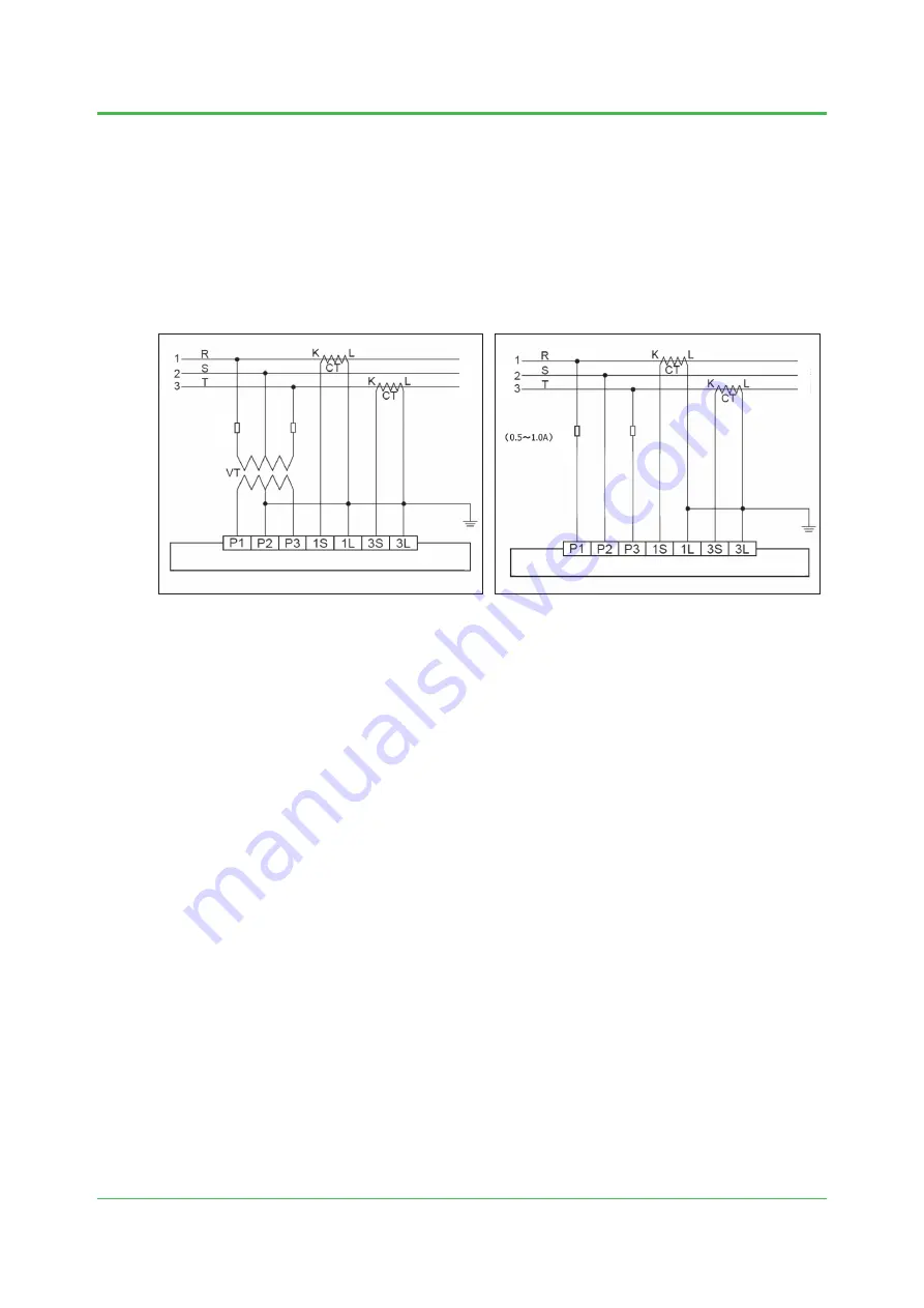
UPM100 Power Monitor wiring example

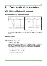
  Wiring without a VT (3 phase 3 wire example)

Note: If not using a VT, do not ground P2.

With a VT

Without a VT

Power supply

Power supply

Load

Fuse

Fuse

Load

This is an example with the UPM100, but the voltage input wiring is also the same on the PR300 

and UPM101.

  Selecting a fuse

If not using a VT, insert a fuse of 0.5–1.0 A into lines P1 and P3.

  Setting the VT and CT ratios

What are the VT and CT ratios?
Generally, when measuring high voltage and high current transformer signals, you use a VT 

(voltage transformer) and CT (current transformer). The ratio between the primary and secondary 

voltage and current ratings are the VT and CT ratios. With these ratios, a power monitor can 

convert the primary voltage and current of the VT and CT and display the electrical quantities.

VT ratio: VT primary/secondary voltage rating
  Ex.: VT ratio = 6600 VAC/110 VAC = 60
CT ratio: CT primary/secondary current rating
  Ex.: CT ratio = 500 AAC/5 AAC = 100

If not using a VT or CT, each ratio is 1.

Summary of Contents for SMARTDAC+ GM

Page 1: ...MARTDAC GM and UPM100 Power Monitoring Package Wiring and Setup Guide TI 77C01H01 01EN TI 77C01H01 01EN Copyright Oct 2018 1st Edition Oct 2018 Yokogawa Electric Corporation 2 9 32 Nakacho Musashino s...

Page 2: ...he contents of this manual in part or in whole be transcribed or copied without our permission Trademarks Our product names or brand names mentioned in this manual are the trademarks or registered tra...

Page 3: ...Blank Page...

Page 4: ...Guide CONTENTS TI 77C01H01 01EN TOFC How to use this manual i 1 Overview 1 1 2 Device configuration and related documents 1 2 3 Package specifications 1 3 4 UPM connection settings 1 4 5 Universal Vie...

Page 5: ...Blank Page...

Page 6: ...g system designed for smallscale applications It consists of the SMARTDAC GM the UPM100 Power Monitor and a CTW fixed wire type current transformer You can also select instruments and communication fu...

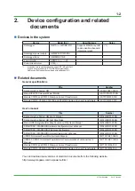
Page 7: ...3 01E Models CTW10 CTW20 CTW100 and CTW130 Clamp on Current Transformers GS 77C01W02 01E User s manual Title Number Data Acquisition System GM User s Manual IM 04L55B01 01EN Data Acquisition System GM...

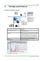
Page 8: ...or Ethernet RS 485 Ethernet converter when using VJET Functions You can acquire watt hours from the power monitor UPM100 and display digital values intetration bar graphs and integral trends on the we...

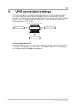
Page 9: ...f integral graphs You can use it with the hardware configurator version 4 05 01 or later and the web application version 4 05 01 or later Hardware Configurator Web Application UPM Connection settings...

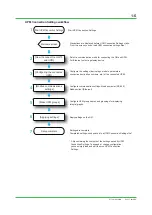
Page 10: ...tarts From this screen you can load UPM connection settings files Apply settings on the GM Settings are complete Completed settings can be saved to a UPM Connection Settings file Setup complete Start...

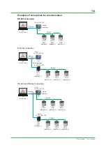
Page 11: ...ernet GM UPM 1 Unit 2 Address 2 UPM 2 Unit 3 Address 3 UPM 3 Unit 4 Address 4 IP 192 168 1 99 IP 192 168 1 100 VJET Server gateway Client IP 192 168 1 1 Unit 1 Address 1 RS 485 and Ethernet connection...

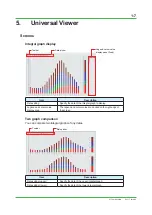
Page 12: ...he date of the integral graph to display Legend and cursor value display area The legend and cursor value are docked on the right edge of the screen Two graph comparison You can compare two integral g...

Page 13: ...lines P1 and P3 n Setting the VT and CT ratios What are the VT and CT ratios Generally when measuring high voltage and high current transformer signals you use a VT voltage transformer and CT current...

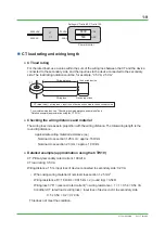
Page 14: ...ance Connected device Device input loss Wiring loss Checking the wiring distance and material The wiring loss increases in proportion with the wiring distance The total wiring length is the round trip...

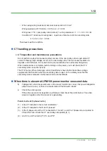
Page 15: ...secondary side connection short The CTW series of fixed wire type current transformers have built in hazardous voltage suppressors that function when the secondary side is open In the unlikely case t...

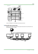
Page 16: ...Check the installation for other phase and wiring schemes as well n Wiring RS 485 communication Wiring for communication between the Data Acquisition System GM and the UPM100 Power Monitor RS 485 4 wi...

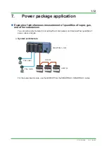
Page 17: ...of quantities of vapor gas and other substances You can add a pulse module for acquiring flow meter pulses and measure flow quantities of power vapor and gas System architecture SMARTDAC GM UPM100 Fl...

Page 18: ...AC GM and UPM100 Power Monitoring Package Wiring and Setup Guide Manual number TI 77C01H01 01EN Oct 2018 1st Edition Newly published Written by Yokogawa Electric Corporation Published by Yokogawa Elec...

Page 19: ...Blank Page...

Reviews: