


1-10
TI 77C01H01-01EN
Oct. 17, 2018-00
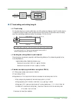
• When using wiring material of nominal cross section 2.00 mm
2
Wiring resistance R =10 Ω/km × 0.015 km × 2 = 0.3 Ω
Wiring loss ≈ I
2
R = (secondary rated current)
2
× wiring resistance = 1 × 1 × 0.3 = 0.3 VA
Condition: CT rated load ≥ wiring loss + input loss of device cnctd. to secondary side
0.5 ≥ 0.3 + 0.2 = 0.5 VA
This does meet the condition.
CT handling precautions
●
CT inspection and maintenance precautions
Do not perform work while measuring lines are live. If the secondary side is open while CT
current is flowing, high voltage occurs on the secondary side. This can cause insulation to
degrade, and if left as-is, can cause burning and accidents and is extremely dangerous.
When maintenance is complete, before turning on the power, you must check the CT’s
secondary side connection (short).
The CTW series of fixed wire type current transformers have built-in hazardous voltage
suppressors that function when the secondary side is open. In the unlikely case that the
secondary side is released, it will prevent burns and accidents.
When there is abnormal UPM100 power monitor measured data
Q. Voltage and current measurements on the power monitor are correct, but power integration
either doesn’t occur, or there are small values. What should I check?
A. Check the active power.
If the active power turns negative or extremely small, check the points below. The active
power is negative when the power is regenerating.
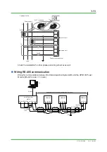
Points to check (3 phase 3 wire)
(1) Is the CT installed in the correct orientation?
(2) Is the CT installed to the R and T phases?
(3) Is the R phase side of the CT connected to 1S and 1L, and the T phase side connected to
3S and SL? Also check the CT secondary side polarity (k, l).
(4) Are R, S, and T wired to P1, P2, and P3?


