


IM 01C25C01-01E
7-3
7. OPERATION
7.3 Starting Operation
After completing the zero point adjustment, follow the
procedure below to start operation.
1) Confirm the operating status. If the output signal
exhibits wide fluctuations (hunting) due to periodic
variation in the process pressure, use the communi-
cator to dampen the transmitter output signal.
Confirm the hunting using a receiving instrument or
the integral indicator, and set the optimum damping
time constant.
2) After confirming the operating status, perform the
following:
IMPORTANT
• Remove the communicator from the terminal
box, and confirm that none of the terminal
screws are loose.
• Close the terminal box cover and the amplifier
cover. Screw each cover in tightly until it will
not turn further.
• There are two covers that must be locked on
the ATEX Flameproof type transmitters. An
Allen head bolt (shrouding bolt) under the edge
of each cover is used to lock the cover. When
the shrouding bolt is driven counterclockwise
with an Allen wrench, the bolt rotates upward
and locks the cover. (See page 8-3.) After
locking the covers, confirm that they are secure
and cannot be opened by hand.
• Tighten the zero-adjustment cover mounting
screw to fix the cover in position.
7.4 Shutting Down Operation
Turn off the power.
NOTE
Whenever shutting down the transmitter for a
long period, detach the transmitter from the tank.
7.5 Venting or Draining Transmit-
ter Pressure-detector Section
Since this transmitter is designed to be self-draining
and self-venting with vertical impulse piping connec-
tions, neither draining nor venting will be required if
the impulse piping is configured appropriately for self-
draining or self-venting operation.
If condensate (or gas) collects in the transmitter
pressure-detector section, the measured pressure may
be in error. If it is not possible to configure the piping
for self-draining (or self-venting) operation, you will
need to loosen the drain (vent) screw on the transmitter
to completely drain (vent) any stagnated liquid (gas).
However, since draining condensate or bleeding off gas
gives the pressure measurement disturbance, this
should not be done when the loop is in operation.
WARNING
Since the accumulated liquid (or gas) may be
toxic or otherwise harmful, take appropriate care
to avoid contact with the body, or inhalation of
vapors.
7.5.1 Draining Condensate
1) Gradually open the drain plug and drain the
transmitter pressure-detector section. (See Figure 7.2)
2) When all accumulated liquid is completely re-
moved, close the drain plug.
3) Tighten the drain plug to a torque of 34 to 39 N·m
{3.5 to 4 kgf·m}.
7.5.2 Venting Gas
1) Gradually open the vent screw to vent gas from the
transmitter pressur-detector section. (See Figure 7.2)
2) When the transmitter is completely vented, close
the vent screw.
3) Tighen the vent screw to a torque of 10 N·m
{1 kgf·m}.
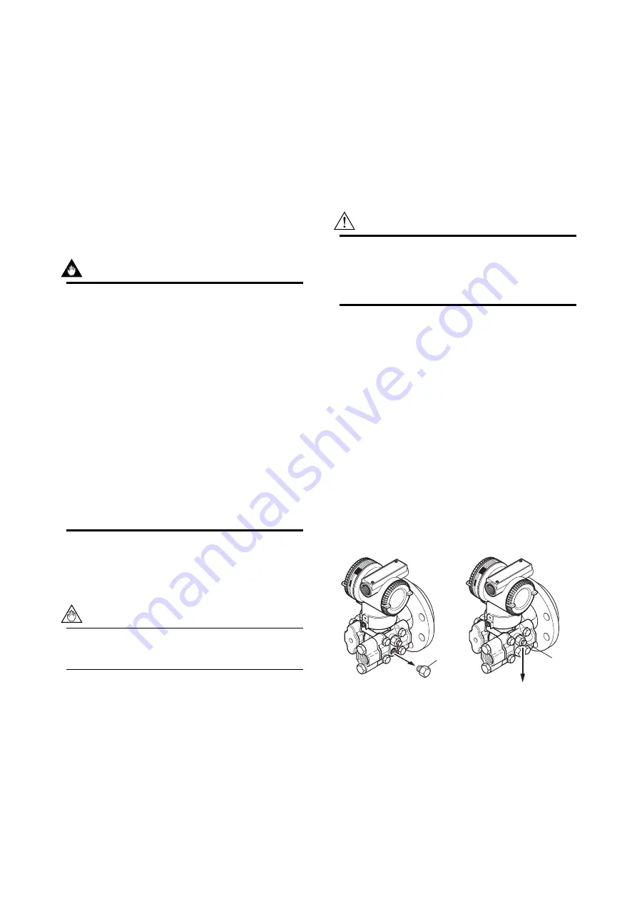
F0705.EPS
Drain plug
When you loosen the drain plug or the vent screw, the accumulated liquid(or gas)
will be expelled in the direction of the arrow.
Vent screw
Figure 7.2
Draining/Venting the Transmitter


