


<5. Wiring>
41
IM 01C25A01-01E
5.2.1 Power Supply Wiring Connection
IMPORTANT
Connecting with the commercial AC power supply
will damage the device. Be sure to use the DC power
supply in the predetermined range.
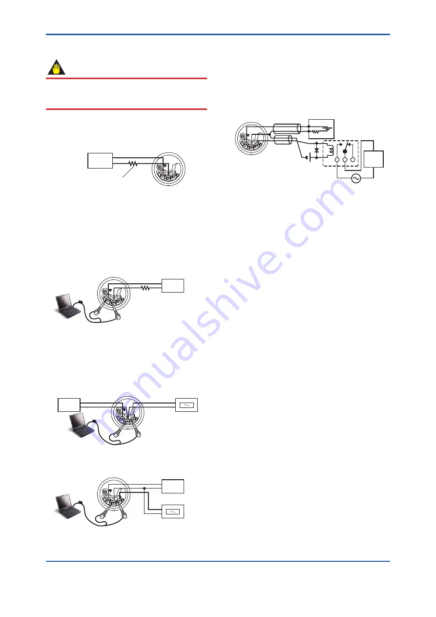
Connect the power supply wiring to the and –
terminals.
Power supply
–
+
Transmitter terminal box
F0502.ai
Load resistance is not
necessary for 1 to 5 V output.
Figure 5.3
Power Supply Wiring Connection
5.2.2 Configuration Tool Connection
■ 4 to 20 mA output, BRAIN / HART
Connect the configuration tool to the and –
terminals. (Use hooks.)
Transmitter terminal box
F0503.ai
Power supply
–
+
Ignore the polarity since
the configuration tool is
AC-coupled to the
terminal box.
USB
FieldMate Modem
PC/FieldMate
Figure 5.4
Configuration Tool Connection
■ 1 to 5 V output, HART
Connect the HART communicator or configuration tool to
the SUPPLY - and VOUT (+) terminals. (Use hooks.)
Transmitter terminal box
F0532.ai
Voltmeter
–
+
Power supply
–
+
USB
FieldMate Modem
PC/FieldMate
Figure 5.5
Four wire connection
Transmitter terminal box
F0533.ai
Power supply
–
+
Voltmeter
–
+
USB
FieldMate Modem
PC/FieldMate
Figure 5.6
Three wire connection
5.2.3 Status Output Connection
When option code /AL is specified, connect the external
wiring as shown in Figure 5.7.
To configure and activate the process alarm function and
status output, it is necessary to set some parameters.
Refer to each communication manual for procedures.
Transmitter
terminal box
Magnetic
valve
AC power supply
External power
supply 30V DC,
120mA max
+
–
250
Ω
24V DC
Use two-wire separately shielded cables.
Distributor
Shielded cable
F0504.ai
Figure 5.7
Status Output Connection


