background image


<7.  Errors and Countermeasures>

55

IM 01C25A01-01E

7. 

Errors and Countermeasures

NOTE

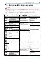
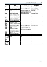
Table 7.1 

Alarm Message Summary (Except EJX910A and EJX930A)

Indicator

Cause

Output Operation

during Error

Countermeasure

None
AL. 01
CAP. ERR

AL. 02
AMP. ERR

AL. 10
PRESS

necessary.

AL. 11
ST. PRSS
AL. 12
CAP. TMP
AL. 13
AMP. TMP
AL. 30
RANGE

Output is outside upper or lower range 

AL. 31
SP. RNG

range.

output.

AL. 35 *

1

P. HI
AL. 36 *

1

P. LO
AL. 37 *

1

SP. HI
AL. 38 *

1

SP. LO
AL. 39 *

1

TMP. HI
AL. 40 *

1

TMP. LO
AL. 50
P. LRV

range.

occurred.

needed.

AL. 51
P. URV
AL. 52
P. SPN
AL. 53
P. ADJ
AL. 54
SP. RNG

needed.

AL. 55
SP. ADJ
AL. 60
SC. CFG

AL. 79
OV. DISP

Summary of Contents for DPharp EJAC50E

Page 1: ...ion 3 1 Mounting 34 3 2 34 35 36 37 38 38 4 Installing Impulse Piping 39 42 115 42 5 Wiring 5 1 Wiring Precautions 44 44 5 3 Wiring 47 49 5 5 Grounding 51 51 6 Operation 6 1 Preparation for Starting Operation 52 52 53 7 Errors and Countermeasures EJX and EJA E Series Differential Pressure and Pressure Transmitters Installation Manual ...

Page 2: ...nual List and Applicable Style Code EJX series Hardware Manual Models Document No Style S3 S1 S2 S2 S2 S1 S2 S1 S2 S1 EJX series Communication Manual Models Document No Style EJA E series Hardware Manual Models Document No Style EJA E series Communication Manual Models Document No Style ...

Page 3: ... 1 Introduction 2 IM 01C25A01 01E Model Document No Regarding This Manual purpose WARNING CAUTION ...

Page 4: ...IM 01C25A01 01E IMPORTANT NOTE 1 1 For Safe Use of Product a Installation WARNING for operators b Wiring WARNING operators c Operation WARNING d Maintenance WARNING e Explosion Protected Type Instrument WARNING location ...

Page 5: ...on 4 IM 01C25A01 01E WARNING g Product Disposal h Authorized Representative in EEA i Control of Pollution Caused by the Product Pb Hg Cd Cr VI PBB PBDE Series GB T26572 GB T26572 SJ T11364 j Morocco conformity mark ...

Page 6: ... 1 Introduction 5 IM 01C25A01 01E 1 2 Warranty installation location Trademarks ...

Page 7: ...luorinated oil 2 EJ 110 EJ 120 EJ 130 EJ 310 EJ 430 EJ 440 1 2 3 4 B D G J K M F0201 1 ai EJX910A EJX930A 1 2 3 4 1 2 3 4 B C D B D G J K M B J EJ 210 1 2 3 4 EJ 510 EJ 530 EJX610A EJX630A EJ 118 EJ 438 F L F0201 2 ai B D J K EJ 115 Mounting bracket Flat type F0202 ai Teflon film Fluorinated oil Bolt Process connector Process connector Gasket U bolt nut U bolt Mounting bracket L type Transmitter m...

Page 8: ...ions 7 IM 01C25A01 01E Check F0203 ai Figure 2 2 Name Plate 2 2 Selecting the Installation Location location 2 3 Pressure Connection WARNING piping 2 4 Installation of an Explosion Protected Instrument CAUTION WARNING ...

Page 9: ... 16 2019 Doc No IFM022 A12 P 1 Yokogawa Electric Corporation Control Drawing Class I II III Division 1 Groups A B C D E F G Class I Zone 0 Group IIC EJX Series Pressure Transmitter Suppl Class I II Division 2 Groups A B C D F G Class III Division 1 Class I Zone 2 Group IIC EJX Series Pressure Transmitter Suppl Refer to Note 4 Associated Apparatus Safety Barrier General Purpose Equipment General Pu...

Page 10: ...pt is used for the interconnection FM approved Associated Nonincendive Field Wiring Apparatus which meets the above conditions must be used as the General Purpose Equipment 5 The General Purpose Equipment connected to the Associated Apparatus must not use or generate a voltage more than Um of the Associated Apparatus 6 The control drawing of the Associated Apparatus must be followed when installin...

Page 11: ... apparatus supply unit In addition the maximum unprotected residual capacitance Ci and inductance Li of each apparatus other than terminators connected to the Fieldbus must be less than or equal to 5 nF and 10 H respectively In each I S Fieldbus segment only one active source normally the associated apparatus is allowed to provide the necessary power for the Fieldbus system The allowed voltage Uo ...

Page 12: ...upply the bus cable must be limited to the range 14 V d c to 17 5 V d c All other equipment connected to the bus cable has to be passive meaning that the apparatus is not allowed to provide energy to the system except a leakage current of 50 A for each connected device Separately powered equipment needs galvanic isolation to ensure the nonincendive field wiring Fieldbus circuit remains passive The...

Page 13: ...ich can be provided by the associated apparatus supply unit In addition the maximum unprotected residual capacitance Ci and inductance Li of each apparatus other than terminators connected to the Fieldbus must be less than or equal to 5 nF In each I S Fieldbus segment only one active source normally the associated apparatus is allowed to provide the necessary power for the Fieldbus system The allo...

Page 14: ...for the Fieldbus system The allowed voltage Uo Voc or Vt of the associated nonincendive field wiring apparatus used to supply the bus cable must be limited to the range 14 V d c to 17 5 V d c All other equipment connected to the bus cable has to be passive meaning that the apparatus is not allowed to provide energy to the system except a leakage current of 50 A for each connected device Separately...

Page 15: ... 2 Handling Cautions 14 IM 01C25A01 01E e FM Intrinsically Safe and Explosion Proof Combination for HART BRAIN Protocol Type a CSA Intrinsically Safe for HART BRAIN Protocol Type Except for EJX9 0A ...

Page 16: ...Class I II Division 2 Groups A B C D F G Class III Division 1 Not Use Safety Barrier Nonincendive CSA Certified Equipment nL or nonincendive Group IIC Zone 2 b CSA Intrinsically Safe for Fieldbus Type Except for EJX9 0A locations Caution for CSA Intrinsically Safe Type Following Contents Refer to DOC No ICS018 Installation Diagram for Intrinsically Safe Division 1 Installation Non Hazardous Locati...

Page 17: ... Following contents refer to DOC No ICS018 Installation Diagram for Non incendive or Type of protection n Division 2 Installation Non Hazardous location Hazardous location F0230 ai Terminator CSA Certified Equipment nL Pressure Transmitter SUPPLY Terminator Transmitter Transmitter Electrical Data ...

Page 18: ...n 1 45 cm Max Sealing Fitting Conduit Transmitter F0208 ai Non Hazardous Locations Hazardous Locations Division 2 Non hazardous Location Equipment 42 V DC Max 4 to 20 mA DC Signal Sealing Fitting Transmitter F0209 ai F0219 ai Three Wire Connection Pressure Transmitters Power Supply Voltmeter SUPPLY SUPPLY Four Wire Connection Pressure Transmitters Power Supply Voltmeter SUPPLY SUPPLY ...

Page 19: ...8 IM 01C25A01 01E d CSA Intrinsically Safe and Explosion proof Combination for HART BRAIN Protocol Type Except for EJX9 0A 1 Technical Data a ATEX Intrinsically Safe for HART BRAIN Protocol Type Except for EJX9 0A apparatus ...

Page 20: ...on Control Drawing Hazardous Location F0210 ai WARNING b ATEX Intrinsically Safe for Fieldbus Type Except for EJX9 0A WARNING NOTE conditions of use Ambient temperature range Process temperature range 6 or later Maximum surface temperature Ambient temperature range Process temperature range Type of O ring ...

Page 21: ... 2 Handling Cautions 20 IM 01C25A01 01E F0239 ai Screw Size Marking ISO M20 1 5 female ANSI 1 2 NPT female M A or W N or ...

Page 22: ... c ATEX Intrinsically Safe for Fieldbus Type for EJX9 0A WARNING Non Hazardous Location Hazardous Location F0232 ai Terminator Safety Barrier Transmitter Pressure Transmitter Transmitter Terminator SUPPLY RTD Pt100 3wire Installation Diagram ...

Page 23: ... 2 Handling Cautions 22 IM 01C25A01 01E Supply circuit or or Sensor circuit d ATEX Flameproof Type ...

Page 24: ...ire Connection Pressure Transmitters Power Supply Voltmeter SUPPLY SUPPLY Four Wire Connection Pressure Transmitters Power Supply Voltmeter SUPPLY SUPPLY WARNING e ATEX Intrinsically Safe and ATEX Flameproof Combination for HART BRAIN Protocol Type Except for EJX9 0A ...

Page 25: ... Apparatus Nonhazardous Area Control Drawing Hazardous Area F0212 ai WARNING apparatus f ATEX Intrinsically Safe Ex ic for Fieldbus Type Except for EJX9 0A Ambient temperature range Process temperature range Type of O ring F0239 ai Screw Size Marking ISO M20 1 5 female ANSI 1 2 NPT female M A or W N or ...

Page 26: ...ons 25 IM 01C25A01 01E 2 Electrical Connection F0214 ai Location of the mark Screw Size Marking ISO M20 1 5 female ANSI 1 2 NPT female M N or W 3 Installation WARNING 4 Operation WARNING 5 Maintenance and Repair WARNING ...

Page 27: ...X Ex ia IIC IIB T4 Ga Ta 40 to 60 C Ex ia IIIC T85 C T100 C T120 C Db Ta 30 15 to 60 C MAX PROCESS TEMP Tp 120 C T85 C Tp 80 C T100 C Tp 100 C T120 C Tp 120 C Enclosure IP66 IP67 FISCO field device IIC IIB WARNING D Tag plate for intrinsically safe Ex ia for Fieldbus Certificate issue number 6 or later 3 WARNING D 3 No KEMA 04ATEX1116 X Ex ia IIC IIB T4 Ga Ta 55 TO 60 C Tp 55 TO 120 C Ex ia IIIC T...

Page 28: ... for EJX9 0A F0236 ai EJX EJA E Series Pressure Transmitters IECEx certified Safety Barrier Supply Hazardous Location Nonhazardous Location Ex ia Group IIC Zone 0 1 1 When using non isolation barrier connect 1 to IS barrier system WARNING b IECEx Intrinsically Safe Ex ic for HART BRAIN Protocol Type Except for EJX9 0A ...

Page 29: ...Pressure Transmitters Associated apparatus Supply Hazardous Location Nonhazardous Location Ex ic WARNING c IECEx Intrinsically Safe Ex ia for Fieldbus Type Except for EJX9 0A WARNING NOTE conditions of use Ambient temperature range Process temperature range 5 or later ...

Page 30: ... 2 Handling Cautions 29 IM 01C25A01 01E F0239 ai Screw Size Marking ISO M20 1 5 female ANSI 1 2 NPT female M A or W N or ...

Page 31: ...ically Safe Ex ic for Fieldbus Type Except for EJX9 0A WARNING NOTE conditions of use Ambient temperature range Process temperature range Type of O ring F0239 ai Screw Size Marking ISO M20 1 5 female ANSI 1 2 NPT female M A or W N or e IECEx Flameproof Type ...

Page 32: ...ower Supply Voltmeter SUPPLY SUPPLY Four Wire Connection Pressure Transmitters Power Supply Voltmeter SUPPLY SUPPLY F0222 ai Location of the mark Screw Size Marking ISO M20 1 5 female ANSI 1 2 NPT female M N or W 2 5 EMC Conformity Standards CAUTION 2 6 Pressure Equipment Directive PED 1 General ...

Page 33: ... 2 Handling Cautions 32 IM 01C25A01 01E 2 Technical Data Model code PS 1 PS V 2 1 6 2 5 2 5 1 6 1 6 1 6 2 5 2 5 3 Operation CAUTION conditions 2 7 EU RoHS Directive AAnnnnnnn AA ...

Page 34: ... 2 Handling Cautions 33 IM 01C25A01 01E 2 8 Safety Requirement Standards 1 Pollution Degree 2 2 Installation Category I 3 Indoor Outdoor use 4 Altitude of installation site ...

Page 35: ...unting Horizontal Impulse Piping Type Vertical pipe mounting Process connector upside Transmitter mounting bolt Mounting bracket U bolt nut U bolt 50 mm 2 inch pipe Vertical pipe mounting Process connector downside F0303 ai Figure 3 3 Transmitter Mounting Vertical Impulse Piping Type Vertical pipe mounting 50 mm 2 inch pipe U bolt L U bolt S Mounting bracket U bolt nut S U bolt nut L Horizontal pi...

Page 36: ...he process The label on each diaphragm seal is marked HIGH or LOW Figure 3 6 Mounting the Diaphragm Seals 3 3 Diaphragm Seals Installation Consideration IMPORTANT F0307 ai 50 mm minimum Minimum liquid level High pressure side Low pressure side The transmitter should be installed as low as possible below the position where the high pressure side diaphragm seal is installed Install the sealed diaphr...

Page 37: ... SW code A 1 4 B C 2 D E 1 92 F0308 ai P Low pressure side High pressure side 0 h Figure 3 8 Example of Installation to Tank Caution on Installation 3 4 Mounting the Flushing Connection Ring 3 4 1 Mounting to Pressure Detector Section Ring holder Spiral gasket F0309 ai View from pressure detector section Groove for installing spiral gasket Pressure detector section Vent Drain plug Ring Figure 3 9 ...

Page 38: ...ure 3 10 Mounting to Process Flange IMPORTANT can slip off and cause injury Table 3 1 Spiral Gasket for Pressure Detector Section Side Part number Size Description K1 K2 K5 K6 IMPORTANT is in an upward position area F0311 ai EJ 210 F9347YD EJ 118 EJ 438 F9347YA 2 inch F9347XA 3 inch Teflon film PART No Diaphragm Fluorinated oil PART No F9145YN Gasket area ...

Page 39: ...ter section Pressure detector section Conduit connection Conduit connection Zero adjustment screw Stopper Figure 3 12 Rotating Transmitter Section Left Side High Pressure Type 3 7 Changing the Direction of Integral Indicator IMPORTANT F0313 ai Figure 3 13 Integral Indicator Direction IMPORTANT 90 90 Integral indicator Mounting screw Amplifier cover LCD board assembly CPU assembly F0314 ai Figure 3...

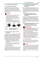
Page 40: ...rocess connector Bolt Differential Pressure Transmitter Figure 4 1 H and L Symbols on a Capsule Assembly 2 Changing the Process Connector Piping Connections for differential pressure transmitters process connectors 57 mm 54 mm 51 mm F0402 ai Figure 4 2 Process Connector Impulse Piping Connection Distances 3 Tightening the Process Connector Mounting Bolts IMPORTANT 4 Removing the Impulse Piping Con...

Page 41: ...t plug optional Stop valve low pressure side Equalizing valve balancing Stop valve high pressure side Figure 4 3 3 Valve Manifold Pipe Mounting Type Direct Mounting Type 3 Valve Manifold Bolts Process connector Gasket Gasket Process connector Bolts Stop valve Stop valve 3 valve manifold 3 valve manifold Equalizing valve Equalizing valve Stop valve Impulse piping Impulse piping Stop valve F0404 ai ...

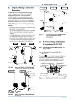
Page 42: ...ing 2 Position of Process Pressure Taps and Transmitter pressure taps process pressure taps 3 Impulse Piping Slope 4 Temperature Difference Between Impulse Piping for differential pressure transmitters 5 Condensate Pots for Steam Flow Measurement for differential pressure transmitters 6 Preventing Wind Speed Effects in Very Low Differential Pressure Measurement for differential pressure transmitte...

Page 43: ...tion Examples EJ 210 F0408 ai Liquid Gas Steam Union or flange Tee Tee Drain plug Drain valve Drain valve Drain plug Union or flange Union or flange Union or flange Tap valve Tap valve Tee Drain valve Drain plug Tap valve Figure 4 8 Impulse Piping Connection Examples for gauge absolute pressure transmitters 4 3 Process Piping Installation Precautions EJ 115 4 3 1 Connecting Process Piping to the T...

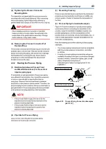
Page 44: ...between Process Fluid and Manifold Locations For the vertical impulse piping type NOTE 2 Pipe Size for Process Piping 3 Preventing Freezing 4 Process Piping Connection Examples conditions application Gas flow measurement Liquid flow measurement Union or flange Union or flange Stop valve Stop valve Manifold Manifold Process piping Process piping F0410 ai Figure 4 10 Process Piping Connection Exampl...

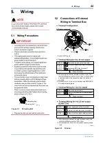
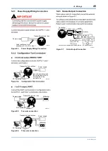
Page 45: ... when AL is specified SUPPLY CHECK or ALARM Ground terminal 1 2 2 2 3 3 F0528 ai SUPPLY VOUT Ground terminal Power supply terminals 1 to 5 V DC with HART communication terminals 1 2 2 3 1 When using an external indicator or check meter the or indicator cannot be connected when AL option is specified 2 Not available for FOUNDATION Fieldbus and PROFIBUS PA communication types SUPPLY CHECK PULSE 1 Wh...

Page 46: ...erminal box USB FieldMate Modem PC FieldMate Transmitter terminal box F0532 ai Voltmeter Power supply USB FieldMate Modem PC FieldMate Figure 5 5 Four wire connection Transmitter terminal box F0533 ai Power supply Voltmeter USB FieldMate Modem PC FieldMate Figure 5 6 Three wire connection 5 2 3 Status Output Connection Transmitter terminal box Magnetic valve AC power supply External power supply 3...

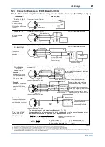
Page 47: ...tion use two wire separately shielded cables This supply voltage requires a power sourse with a maximum output current of no less than E R Distributor or communication medium ex EP card or communication medium ex EP card Electric counter B Shielded Cable Transmitter Electrical Terminal When analog and pulse output are used the length of communication line is subjected to wiring conditions Refer to...

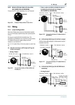
Page 48: ...X910A and EJX930A Hazardous Location Nonhazardous Location Transmitter terminal box Distributor Power supply unit Receiver instrument Receiver instrument F0507 ai Figure 5 10 Connection between Transmitter and Distributor 2 Intrinsically Safe Type 4 to 20 mA output Hazardous Location Nonhazardous Location Transmitter terminal box Distributor Power supply unit Receiver instrument Safety barrier F05...

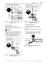
Page 49: ...ansmitter terminal box Distributor Power supply unit Receiver instrument Figure 5 13 Connection between Transmitter Distributor and Receiver Four wire connection Hazardous Location Nonhazardous Location Transmitter terminal box Distributor Power supply unit Receiver instrument F0530 ai Figure 5 14 Connection between Transmitter Distributor and Receiver 5 3 2 Wiring Installation 1 General use Type ...

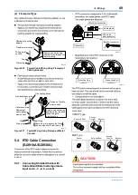
Page 50: ...of flexible metal conduit Apply a non hardening sealant to the threads of these fittings for waterproofing After wiring impregnate the fitting with a compound to seal tubing Figure 5 17 Typical Wiring Using Flameproof Metal Conduit 5 4 RTD Cable Connection EJX910A EJX930A is used 5 4 1 Connecting Shielded Cable with Cable Gland External temperature input code 1 2 3 and 4 Transmitter Cable gland El...

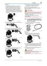
Page 51: ...M 01C25A01 01E Procedure connection F0517 ai F0518 ai F0519 ai F0520 ai F0521 ai CAUTION 5 4 2 Connecting Shielded Cable for Con duit Use External temperature input code B C and D F0522 ai Procedure F0523 ai CAUTION ...

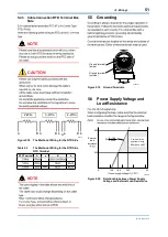
Page 52: ...thod of Wiring for the RTD Side RTD Terminal RTD Terminal A a B b open NOTE type 5 5 Grounding Ground terminal inside Ground terminal outside F0525 ai Figure 5 19 Ground Terminals 5 6 Power Supply Voltage and Load Resistance 600 250 0 10 5 16 6 25 2 42 External load resistance F0526 ai Communication applicable range BRAIN and HART R E 10 5 0 0244 Figure 5 20 Relationship between Power Supply Volta...

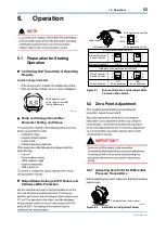
Page 53: ...02 ai H L H L Slide switch CPU assembly BO H L WR E D Burnout direction switch Write protection switch H L H L E D E D Hardware write protection switch WR Write Protection Switch Position HIGH LOW Burnout direction switch BO Burnout Direction Burnout Direction Switch Position YES Write disabled NO Write enabled Write Protection Figure 6 1 Burn out Direction and Hardware Write Protection Slide Swit...

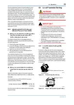
Page 54: ... cannot obtain the Low Range Value from the actual measured value of 0 130 50 250 50 Actual measured value x100 40 0 10 4mA 6 3 Local Parameter Setting WARNING location IMPORTANT setting procedure 6 3 1 Local Parameter Setting LPS Overview is carried out External adjustment screw cover F0604 ai Figure 6 3 External Adjustment Screw Integral indicator Push button F0605 ai Figure 6 4 Range Setting Sw...

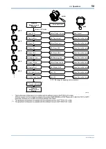
Page 55: ...value 7 Output Mode 3 Press Unit 2 Tag Number 4 Press LRV 5 Press URV 8 Display Out1 9 LRV Apply Press 10 URV Apply Press 6 Damping Time Select Output mode Select Press unit Edit Tag number Edit Press LRV Edit Press URV Edit Display Out1 Set LRV Set URV Edit Damping time Process Measurement Display Zero adjustment 9 10 Re range by applying actual pressure Process Measurement Display 11 Device Info...

Page 56: ...rmeasure None AL 01 CAP ERR AL 02 AMP ERR AL 10 PRESS necessary AL 11 ST PRSS AL 12 CAP TMP AL 13 AMP TMP AL 30 RANGE Output is outside upper or lower range AL 31 SP RNG range output AL 35 1 P HI AL 36 1 P LO AL 37 1 SP HI AL 38 1 SP LO AL 39 1 TMP HI AL 40 1 TMP LO AL 50 P LRV range occurred needed AL 51 P URV AL 52 P SPN AL 53 P ADJ AL 54 SP RNG needed AL 55 SP ADJ AL 60 SC CFG AL 79 OV DISP ...

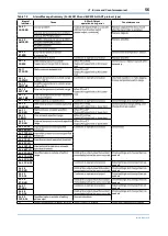
Page 57: ...AL 10 PRESS necessary AL 11 ST PRSS AL 12 CAP TMP AL 13 AMP TMP AL 14 EXT TMP AL 15 EXT TMP AL 16 PLS AL 30 PRS RNG range AL 31 SP RNG range AL 32 F RNG AL 33 ET RNG range AL 35 P HI AL 36 P LO AL 37 SP HI AL 38 SP LO AL 41 F HI AL 42 F LO AL 43 ET HI AL 44 ET LO AL 50 P LRV range needed AL 51 P URV AL 52 P SPN AL 53 P ADJ needed AL 54 SP RNG needed AL 55 SP ADJ needed AL 56 ET RNG needed AL 57 ET...

Page 58: ...setting AL 87 FLG LO AL 88 INVR DP out AL 88 INVR SL AL 88 INVR SH AL 88 INVR F AL 89 ILBD OV AL 89 B BLK detected setting AL 89 H BLK detected AL 89 L BLK detected AL 89 H LRG pressure side is large AL 89 L LRG pressure side is large AL 89 A BLK detected AL 90 SIM AL 91 F SIM Value AL 91 P SIM AL 91 SP SIM AL 91 ET SIM AL 91 TF SIM AL 91 PCT SIM AL 91 AO SIM ...

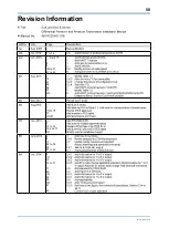
Page 59: ...5A01 01E Revision Information Page 1st 2nd 7 to 14 3rd 1 2 3 41 to 43 1 14 27 28 36 37 1 17 7 13 to 14 16 and 17 2 8 17 28 to 34 28 37 to 42 5 2 1 Add note for power supply 8 13 16 to 17 17 29 33 36 41 42 6 3 11 ...

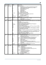
Page 60: ...59 IM 01C25A01 01E Page 1 2 3 5 6 7 to 28 28 51 26 to 31 26 53 1 4 6 8 to 12 16 to 23 16 17 23 24 27 28 for code Z safe type 1 8 to 13 11 21 28 28 31 9 14 15 17 18 19 22 24 26 33 ...

Reviews: