<2. Handling Cautions>
10
IM 01C25A01-01E
Model: EJX-F Series
Date: January 27, 2005
Rev.4: July 16, 2019
Doc. No.:
IFM024-A12 P.2
Yokogawa Electric Corporation
IFM024
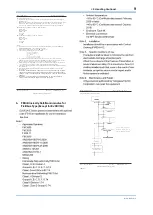
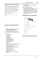
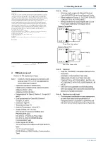
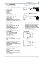
Specific conditions of use:
-
Precautions shall be taken to minimize the risk from electrostatic discharge of
painted parts.
-
When the enclosure of the Pressure Transmitters is made of aluminum alloy, if it is
mounted in Zone 0, it shall be installed such that, even in the event of rare incidents,
an ignition source due to impact and/or friction sparks is excluded.
Entity parameters [Groups: A, B, C, D, E, F, G, and IIC]
Ui: 24 V
Ii: 250 mA
Pi: 1.2 W
Ci: 3.52 nF
Li: 0 µH
FISCO parameters (1) [Groups: A, B, C, D, E, F, G, and IIC]
Ui: 17.5 V
Ii: 380 mA
Pi: 5.32 W
Ci: 3.52 nF
Li: 0 µH
FISCO parameters (2) [Groups: C, D, E, F, G, and IIB]
Ui: 17.5 V
Ii: 460 mA
Pi: 5.32 W
Ci: 3.52 nF
Li: 0 µH
Notes:
1.
Installation must be in accordance with the National Electric Code (NFPA70),
ANSI/ISA-RP12.06.01, and relevant local codes.
2.
The Associated Apparatus and the Terminators must be FM-approved.
3.
The following conditions must be satisfied.
Ui
Isc
i
i
4.
General Purpose Equipment connected to the Associated Apparatus must not use or
generate a voltage more than Um of the Associated Apparatus.
5.
The control drawing of the Associated Apparatus must be followed when installing the
equipment.
6.
Dust-tight conduit seals must be used when installed in Class II or Class III
environments.
7.
WARNING –ELECTROSTATIC CHARGE MAY CAUSE AN EXPLOSION HAZARD.
AVOID ANY ACTIONS THAT CAUSE THE GENERATION O F ELECTROSTATIC
CHARGE, SUCH AS RUBBING WITH A DRY CLOTH ON COATING FACE OF THE
PRODUCT.
8.
WARNING – SUBSTITUTION OF COMPONENTS MAY IMPAIR INTRINSIC SAFETY
AND SUITABILITY FOR HAZARDOUS LOCATION
Model: EJX-F Series
Date: May 9, 2006
Rev.1: July 16, 2019
Doc. No.:
IFM024-A12 P.2-1
Yokogawa Electric Corporation
IFM024
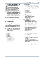
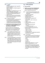
FISCO Rules
The FISCO Concept allows the interconnection of intrinsically safe apparatus to associated apparatus
not specifically examined in such combination. The criterion for such interconnection is that the
voltage (Ui), the current (Ii) and the power (Pi) which intrinsically safe apparatus can receive and
remain intrinsically safe, considering faults, must be equal or greater than the voltage (Uo, Voc or Vt),
the current (Io, Isc or It) and the power (Po) which can be provided by the associated apparatus
(supply unit). In addition, the maximum unprotected residual capacitance (Ci) and inductance (Li) of
each apparatus (other than terminators) connected to the Fieldbus must be less than or equal to 5 nF
and 10 H respectively.
In each I.S. Fieldbus segment only one active source, normally the associated apparatus, is allowed to
provide the necessary power for the Fieldbus system. The allowed voltage (Uo, Voc or Vt) of the
associated apparatus used to supply the bus cable must be limited to the range of 14 V d.c. to 17.5 V d.c.
All other equipment connected to the bus cable has to be passive, meaning that the apparatus is not
allowed to provide energy to the system, except a leakage current of 50
Separately powered equipment needs galvanic isolation to ensure the intrinsically safe Fieldbus
circuit remains passive.
The cable used to interconnect the devices needs to comply with the following parameters:
Loop resistance R': 15....150 /km
Inductance per unit length L': 0.4....1 mH/km
Capacitance per unit length C': 45....200 nF/km C' = C' line/line + 0.5 C' line/screen, if both lines are
floating or C' = C' line/line + C'line/screen, if the screen is connected to one line.
Length of spur cable: max. 60 m
Length of trunk cable: max. 1 km in IIC and 5 km in IIB
Length of splice: max = 1 m
Terminators
At the end of each trunk cable an FM Approved line terminator with the following parameters is
suitable:
R = 90...100
C = 0 ....2.2 F
Model: EJX-F Series
Date: January 27, 2005
Rev.1: July 16, 2019
Doc. No.:
IFM024-A12 P.3
Yokogawa Electric Corporation
IFM024
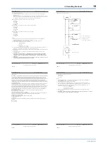
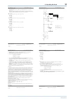
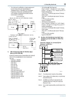
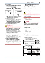
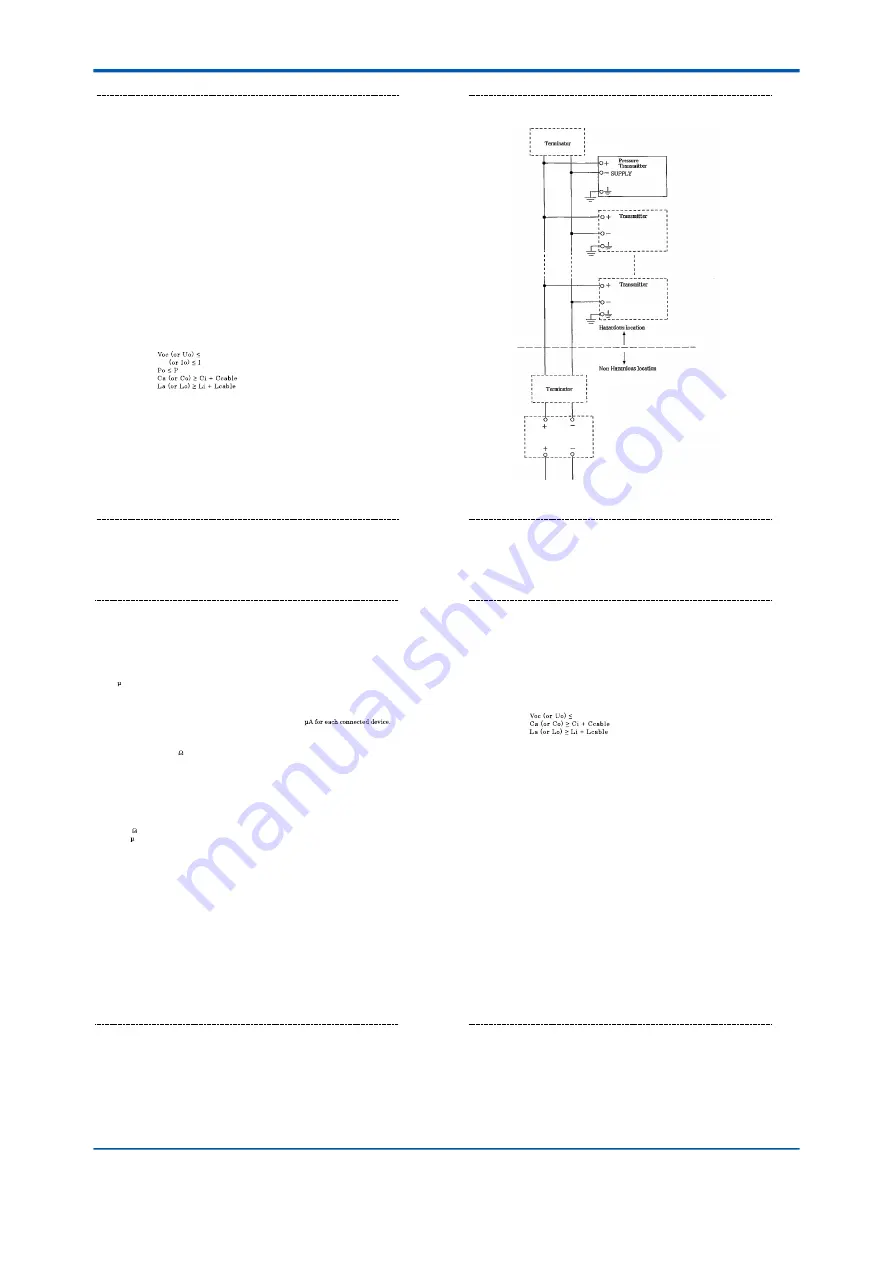
General Purpose
Equipment
Control drawing (nonincendive)
Class I, II, Division 2
Groups A, B, C, D , F, G
Class III, D ivision 1
Class I, Zone 2, G roup IIC
(Refer to Note 3)
Model: EJX-F Series
Date: January 27, 2005
Rev.5: July 16, 2019
Doc. No.:
IFM024-A12 P.4-1
Yokogawa Electric Corporation
IFM024
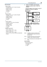
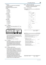
Nonincendive field wiring parameters
Vmax: 32 V
Ci: 3.52 nF
Li: 0 µH
Notes:
1.
Installation must be in accordance with the National Electric Code (NFPA70),
ANSI/ISA-RP12.06.01, and relevant local codes.
2.
The following conditions must be satisfied.
3.
In case Nonincendive Field Wiring Concept is used for the interconnection,
FM-approved Associated Nonincendive Field Wiring Apparatus, which meets the
following conditions, must be used as the General Purpose Equipment. The
Terminators also must be FM approved.
Vmax
4.
Dust-tight conduit seals must be used when installed in Class II or Class III
environments.
5.
WARNING – SUBSTITUTION OF COMPONENTS MAY IMPAIR INTRINSIC SAFETY
AND SUITABILITY FOR HAZARDOUS LOCATION


