<5. Wiring>
45
IM 01C25A01-01E
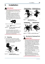
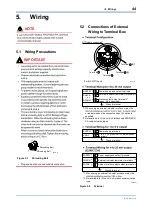
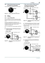
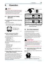
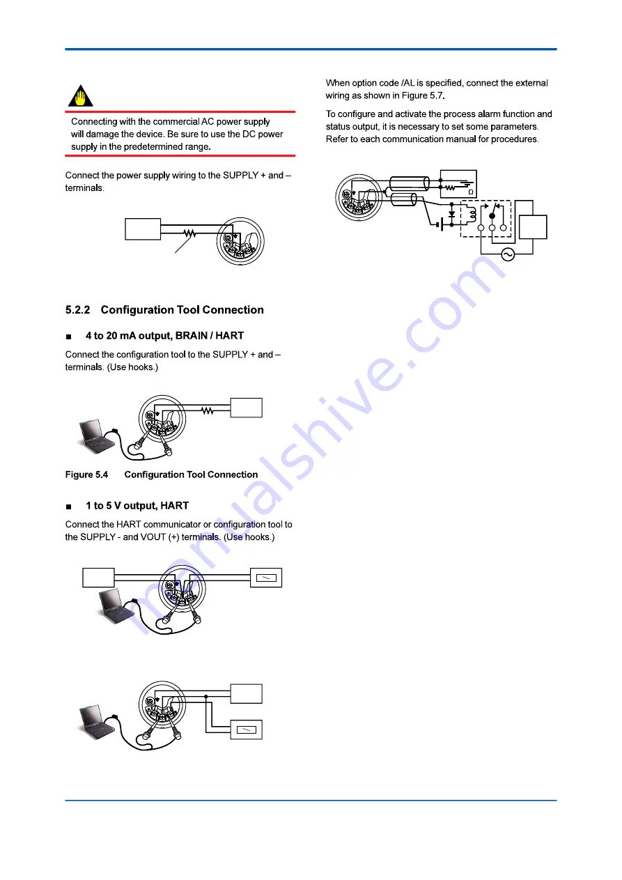
5.2.1 Power Supply Wiring Connection
IMPORTANT
Power supply
–
+
Transmitter terminal box
F0502.ai
Load resistance is not
necessary for 1 to 5 V output.
Figure 5.3
Power Supply Wiring Connection
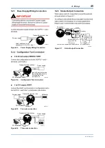
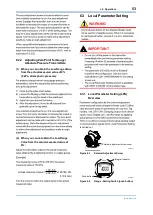
Transmitter terminal box
F0503.ai
Power supply
–
+
Ignore the polarity since
the configuration tool is
AC-coupled to the
terminal box.
USB
FieldMate Modem
PC/FieldMate
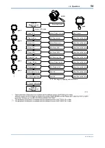
Transmitter terminal box
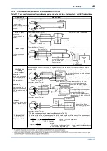
F0532.ai
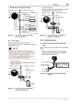
Voltmeter
–
+
Power supply
–
+
USB
FieldMate Modem
PC/FieldMate
Figure 5.5
Four wire connection
Transmitter terminal box
F0533.ai
Power supply
–
+
Voltmeter
–
+
USB
FieldMate Modem
PC/FieldMate
Figure 5.6
Three wire connection
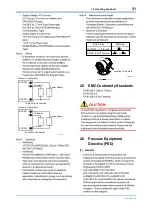
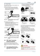
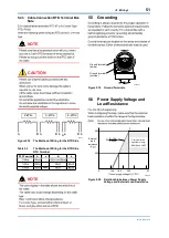
5.2.3 Status Output Connection
Transmitter
terminal box
Magnetic
valve
AC power supply
External power
supply 30V DC,
120mA max
+
–
250
24V DC
Use two-wire separately shielded cables.
Distributor
Shielded cable
F0504.ai
Figure 5.7
Status Output Connection