YOKOGAWA AQ6375 Getting Started Manual Download Page 25

25

IM AQ6375-02EN

Explanation

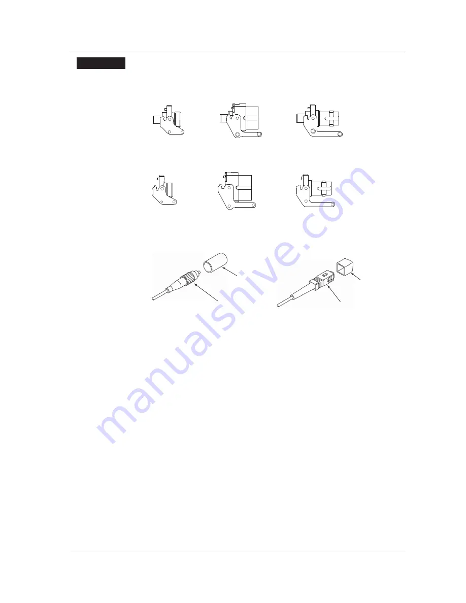
Types of Connector Adapter

The connector adapter for internal reference light output (AQ9441) comes in the following 
three types. 


FC type

SC type

ST type

The optical input connector adapter (AQ9447) comes in the following three types. 


SC type

ST type

FC type

Optical Connectors Types

The instrument can use FC, SC, or ST type optical connectors. 


FC type optical

connector

Cap


SC type optical

connector

Cap

6  Attaching the Connector Adapter

Summary of Contents for AQ6375

Page 1: ...User s Manual AQ6375 Optical Spectrum Analyzer Getting Started Guide IM AQ6375 02EN 3rd Edition ...

Page 2: ...asing YOKOGAWA products YOKOGAWA provides registered users with a variety of information and services Please allow us to serve you best by completing the product registration form accessible from our homepage http tmi yokogawa com PIM 103 03E ...

Page 3: ...Optical Spectrum Analyzer Getting Started Guide IM AQ6375 02EN This manual Explains instrument handling precautions and basic operating procedures Notes The contents of this manual are subject to change without prior notice as a result of improvements in the instrument s performance and functions Display contents illustrated in this manual may differ slightly from what actually appears on your scr...

Page 4: ...ated voltage 250 V H GB standard power cord complies with the CCC part no A1006WD maximum rated voltage 250 V M UL CSA standard power cord with 3P 2P converter part no A1006WD maximum rated voltage 125 V Options FC AQ9447 FC connector adapter for optical input SC AQ9447 SC connector adapter for optical input ST AQ9447 ST connector adapter for optical input RFC AQ9441 FC universal adapter for calib...

Page 5: ...C type for optical input 810804602 SCC SC type for optical input 810804602 STC ST type for optical input AQ9441 universal adapter 813917321 FCC FC type for calibration light source output 813917321 SCC SC type for calibration light source output 813917321 STC ST type for calibration light source output Printer roll paper B9988AE Lot size is 10 rolls 10 meters each ...

Page 6: ...tection provided by the instrument may be impaired Yokogawa Electric Corporation assumes no liability for the customer s failure to comply with these requirements The following symbols are used on this instrument Danger Refer to the user s manual This symbol appears on dangerous locations on the instrument which require special instructions for proper handling or use The same symbol appears in the...

Page 7: ...ower cord that comes with the instrument is a three prong type power cord Connect the power cord to a properly grounded three prong outlet Do not Impair the Protective Grounding Never cut off the internal or external protective earth wire or disconnect the wiring of the protective earth terminal Doing so poses a potential shock hazerd Do not Operate with Defective Protective Grounding or Fuse Do n...

Page 8: ...ly Safety Precautions for Laser Products This instrument uses a laser light source This instrument is a Class 1 laser product as defined by IEC 60825 1 Safety of Laser Products Part 1 Equipment Classification Requirements and User s Guide CLASS 1 LASER PRODUCT Laser Class 1 Label If the laser output is observed at a distance of 100mm or less from the laser beam emitting part by means of optical me...

Page 9: ...rective Annex 1 this product is classified as a Monitoring and Control instrumentation product Do not dispose in domestic household waste When disposing products in the EU contact your local Yokogawa Europe B V office New EU Battery Directive New EU Battery Directive DIRECTIVE 2006 66 EC This directive is valid only in the EU Batteries are included in this product This marking indicates they shall...

Page 10: ...r s data and precautions that can be taken to prevent such occurrences Note Calls attention to information that is important for proper operation of the instrument Notations Used on Pages Describing Operating Procedures On pages that describe the operating procedures the following notations are used to distinguish the procedures from their explanations Procedure This subsection contains the operat...

Page 11: ...Auto Sweep Setting and Measurement Other Settings Waveform Display Displaying Calculated Waveforms Marker Display Searching Waveform Analysis Waveform Analysis GO NO GO Judgment Saving Display Data and Printing Out Storage Media Saving Data Internal Printer Optional Section 3 1 Section 3 4 Section 3 7 Section 5 1 Section 5 2 to 5 11 Section 6 1 to 6 4 Section 6 5 Section 6 8 Section 6 12 Section 7...

Page 12: ......

Page 13: ...tive ix Symbols and Notation Used in This Manual x Flow of Operation xi 1 Front Panel 15 2 Rear Panel 16 3 Panel Keys and Knobs 17 4 LCD Screen 20 5 Installing the Instrument 22 6 Attaching the Connector Adapter 24 7 Connecting a Communication Interface 26 8 Turning the Power ON OFF 29 9 Connecting the DUT 34 10 Specifications 35 11 External Dimensions 38 ...

Page 14: ......

Page 15: ...t side of the LCD display 3 FUNCTION section Used to enter settings pertaining to all measurements sweep measurement conditions data analysis and various functions 4 DATA ENTRY section Used for measurement condition parameter input label input etc 5 POWER Used to start and shut down the instrument 6 USB interface Used to connect USB storage media 7 UNDO LOCAL See the following table 3 Panel keys a...

Page 16: ...r controlling an external device 3 SERIAL RS 232 interface 4 TRIGGER IN Input connector for synchronous signals for the synchronous measurement function with the Tunable Laser Source 5 TRIGGER OUT Output connector for synchronous signals for the synchronous measurement function with the Tunable Laser Source 6 ANALOG OUT Analog output 7 MAIN POWER Used to turn the main power ON OFF 8 Power cord con...

Page 17: ... functions related to level axis settings When you press the LEVEL key the soft key menu for setting reference level appears SETUP The SETUP key contains functions related to measurement condition settings ZOOM The ZOOM key contains the zoom function which allows the user to freely enlarge or reduce a measured waveform in order to check a small area of the measured waveform or to check the overall...

Page 18: ...ut the measurement screen to the internal printer or a file When you press the COPY key the measured waveforms and lists displayed on the screen are output to the internal printer or a file The FEED key is used to feed printer paper Paper feeding continues as long as you hold down the FEED key UNDO LOCAL The key s function changes depending on the status of the instrument when the UNDO LOCAL key i...

Page 19: ...se step for numerical values Each time you press this key the setting toggles between ON and OFF When ON the lamp lights Numeric keypad You can enter numerical values directly into the parameter input window by pressing keys of the numeric keypad After you have pressed a parameter soft key to display the current setting in the parameter display area you can press a numeric keypad key to display th...

Page 20: ...ength resolution 9 Displays measurement sensitivity 10 Displays averaging times 11 Displays the number of measurement samples 12 Displays date and time 13 Displays each trace status 14 Only displayed when ZOOM function is used 15 Displays the statuses of main settings When a setting is ON its display is depressed or is displayed with white on black background if the display colors are black and wh...

Page 21: ...21 IM AQ6375 02EN 19 Parameter display area 20 Parameter input area 21 OVERVIEW display screen Only displayed when ZOOM function is used 22 Displays sub scale 4 LCD Screen ...

Page 22: ... transport This can adversely affect the accuracy of the internal monochromator and inhibit performance When unpacking When the instrument is packaged in a box and moved prevent condensation by allowing sufficient time for the instrument to acclimatize before removing it from the box Installation Conditions Install the instrument so that the following conditions are met Flat Horizontal Location Pl...

Page 23: ...n is high In an unstable place Where the instrument is exposed to water or other liquids General Handling Precautions Do Not Place Anything on Top of the Instrument Never stack instruments or place any other objects on top of the instrument especially those containing water Doing so can lead to malfunction Do Not Apply Shock to the Instrument Take Proper Care When Carrying the Instrument The instr...

Page 24: ...r adapter s lock lever up The lock lever s lock is released 3 Pull the connector adapter all the way out 4 Close the optical connector cover at the front of the instrument Panel Lock lever Ferrule Latch pin Optical input section Connector adapter Attached CAUTION As there may be dust adhering to calibration output be sure to clean it before attaching the connector adapter Do not exhale or blow com...

Page 25: ...n the following three types FC type SC type ST type The optical input connector adapter AQ9447 comes in the following three types SC type ST type FC type Optical Connectors Types The instrument can use FC SC or ST type optical connectors FC type optical connector Cap SC type optical connector Cap 6 Attaching the Connector Adapter ...

Page 26: ...same time In addition to a mouse you can connect a USB storage device Supported PS 2 Mouse The PS 2 wheel mouse by Microsoft Corporation is recommended for this instrument Connections The PS 2 mouse is connected to the KBD interface PS 2 terminal on the rear panel of the instrument through the keyboard 1 Confirm that the MAIN POWER switch on the rear panel is OFF 2 Orient the keyboard with the PS ...

Page 27: ...D connector PS 2 terminal on the rear panel of the instrument 1 Confirm that the MAIN POWER switch on the rear panel is OFF 2 Orient the PS 2 keyboard to match the direction of the connector then connect to the KBD connector on the rear panel TRIGGER IN TRIGGER OUT ANALOG OUT GP IB1 IEEE488 1 488 2 GP IB2 IEEE488 1 FOR TLS ETC WARNING Do not operate without reading the safety precautions in the us...

Page 28: ...USB POWER USB connector Removing See section 8 1 of IM AQ6375 01EN Using the REMOVE USB STORAGE soft key CAUTION Do not remove the USB storage device or turn the power OFF while the USB storage device access indicator is blinking This can damage the data on the device or the device itself Connecting with Other Devices You can use the GP IB RS 232C or Ethernet interface to connect other external in...

Page 29: ...ot provide appropriate protective grounding Preparing to Turn ON the Power The AQ6375 has a MAIN POWER switch for turning the main power ON OFF and a POWER switch for starting and shutting down the instrument The POWER switch is a push button switch press once to turn it ON and press again to turn it OFF Confirm that the MAIN POWER switch on the rear panel of the instrument is OFF Connect the powe...

Page 30: ...s orange OF F MA IN PO WE R ON 100 240 V AC 150 VA MA X 50 60H z FU SE 250 V T 5A 3 Press the POWER switch on the front panel of the instrument The color of the switch turns from orange to green The operating system starts up and initialization of the instrument begins US B PO WER The initialization screen appears and the internal initialization process starts STEP 1 9 through STEP 9 9 are display...

Page 31: ...justment after a one hour warm up When the Power on Operation Does Not Finish Normally Turn off the power switch and check that The instrument is installed properly See section 3 1 installing the instrument The power cord is connected properly See the previous page If the instrument still does not work properly contact your nearest YOKOGAWA dealer for repairs If an error occurs in the memory or so...

Page 32: ... along with the YES and NO soft keys 2 Press the YES soft key The message AQ6375 is shutting down Please wait appears and shut down begins If you do not wish to shut down press the NO soft key The screen returns to the original soft key menu 3 After the POWER switch changes from green to orange turn OFF the MAIN POWER switch on the rear panel of the instrument CAUTION Do not cut the power to the i...

Page 33: ...he POWER switch changes from green to orange turn OFF the MAIN POWER switch on the rear panel of the instrument Note If for some reason the instrument fails to shut down normally hold down the POWER switch for approximately four seconds or longer to force standby mode Note that the operating system configuration file will not be backed up possibly resulting in malfunctions upon start up the next t...

Page 34: ...nector with the plug inserted at a slanted angle Doing so may damage the instrument s optical connector s components or the connector itself Before connecting the input light make sure that it does not exceed the AQ6375 s maximum rated level If input light exceeding the maximum rated level is introduced the optical section may be damaged Press the optical connector hard against the cleaning surfac...

Page 35: ...2 4 6 0 1 dB 1550 nm Sweep time1 7 8 0 5 s NORM_AUTO 1 s NORMAL 10 s MID 20 s HIGH1 60 s HIGH2 600 s HIGH3 Function Automatic measurement Program function 64 programs 200 steps Setting of measuring conditions Center wavelength span wavelength sampling points wavelength resolution measurement sensitivity averaging times 1 to 999 sweep single repeat AUTO automatically sets measuring conditions sweep...

Page 36: ...gth reference light source output AQ9441 universal adapter optional required Connector types FC SC ST Printer Built in thermal printer factory option Display12 10 4 color LCD resolution 800 x 600 pixels Power requirement 100 to 240 VAC 50 60 Hz approximately 150 VA Environment conditions Operating temperature range 5 to 35 C Operating humidity range 10 to 50 C Ambient humidity 80 RH or less no con...

Page 37: ... 9 5 μm NA 0 104 to 0 107 6 With the resolution setting of 0 1 nm at ambient temperature of 23 3 C 7 Pulse light measurement mode OFF TLS synchronous sweep mode OFF 8 Span 100 nm or less wavelength sampling points 1001 averaging times 1 9 Sensitivity HIGH 1 HIGH2 or HIGH3 10 Automatically goes to CHOP mode when HIGH1 HIGH2 or HIGH3 is selected 11 Note that this excludes the protector and handle 12...

Page 38: ... 18 06 1 26 REAR VIEW If not specified the tolerance is 3 However in cases of less than 10 mm the tolerance is 0 3 mm TRIGGER IN TRIGGER OUT ANALOG OUT SERIAL RS 232 ETHERNET 10 100BASE TX VIDEO OUT SVGA KBD GP IB1 IEEE488 1 488 2 GP IB2 IEEE488 1 FOR TLS ETC MAIN POWER ON OFF 100 240V AC 150VA MAX 50 60Hz FUSE 250V T 5A USB USB ...

Reviews: