YOKOGAWA 735201 User Manual Download Page 48

 4.3  List of Commands


IM 735201-01E


4-8


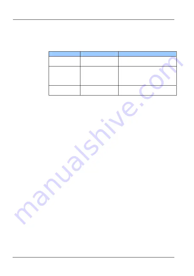
Communication Errors 

If a communication error occurs in remote control, a string comprising “ERR” plus 
a number is sent.     

 
Error List 

Error Number


Description


Cause


ERR1


Command syntax 
error


Command not correct.


ERR2


Command 
execution error


Parameters out of range.   
Appears when in a mode that 
precludes execution of the 
command


ERR3


System abnormality 
error


Memory damaged, or other 
hardware related trouble.   


Summary of Contents for 735201

Page 1: ...User s Manual IM 735201 01E 3rd Edition Model 735201 TB200 OPTICAL POWER METER ...

Page 2: ...ou have any questions or find any errors please contact your nearest YOKOGAWA dealer as listed on the back cover of this manual Copying or reproducing all or any part of the contents of this manual without the permission of Yokogawa Electric Corporation is strictly prohibited A warranty sheet is included It cannot be reissued After reading the sheet keep it in a safe location Trademarks Windows is...

Page 3: ...ee who purchases the Licensed Software on the condition that the Licensee consents to agree to the terms and conditions stipulated herein 1 2 The Licensed Software herein shall mean and include all applicable programs and documentation without limitation all proprietary technology algorithms and know how such as a factor invariant or process contained therein Article 2 Grant of License 2 1 Yokogaw...

Page 4: ...S OFMERCHANTABILITYOR FITNESS FORAPARTICULAR PURPOSEARE HEREBYDISCLAIMED BYYOKOGAWAANDALLTHIRD PARTIES LICENSINGTHIRD PARTYSOFTWARETOYOKOGAWA 4 6 Correction of nonconformity in the manner and for the period of time provided above shall be the Licensee s sole and exclusive remedy for any failure ofYokogawa to comply withits obligations and shall constitute fulfillment of all liabilities of Yokogawa...

Page 5: ...ndirectly export or transfer the Licensed Software to any countries other than those whereYokogawa permits export in advance Article 8 Term ThisAgreement shall become effective on the date when the Licensee receives the Licensed Software and continues in effect unless or until terminated as provided herein or the Licensee ceases using the Licensed Software by itself or withYokogawa s thirty 30 day...

Page 6: ...ler or representative Models and Suffix Codes Model Suffix Code Description 735201 Power cord M C F G J AC adapter PSE Conforming 2 pin AC adapter UL CSAcompliant UL2P AC adapter VDE compliant CEE C2 AC adapter AS compliant AS2P AC adapter BS compliant BS2P angle With without sensor head CA0 CA1 CA3 Without sensor head when ordering main unit only With sensor head 405 nm 1 wavelength calibration I...

Page 7: ...urchasing together with the TB200 Software TB200 Utility 1 Available on the sensor head accessory CD Sensor protective cap 1 Attached to the sensor head Note The model when purchasing the sensor head by itself is 735221 Options Sold Separately The following options are available for purchase separately Name Model Notes Sensor head 735221 Model when ordering only the sensor head Protector SU2002A P...

Page 8: ...implies any warranty against damages occurring as a result of failure to take these precautions The following safety symbols and wording is used in this manual Warning Handle with care Refer to the user s manual or service manual This symbol appears on dangerous locations on the instrument which require special instructions for proper handling or use The same symbol appears in the corresponding pl...

Page 9: ...posure to radiation from lasers operate the item under test strictly according to the device s user s manual Also take care when handling the lens and other optical devices as doing so can cause damage to the eye To prevent fire or electric shock do not insert or drop metallic objects into the opening When connecting to commercial power connect directly to a dedicated outlet Do not use extension c...

Page 10: ...power cord from the outlet during lightning storms Fire electric shock or malfunction can result Do not use old and new batteries at the same time Explosion or leakage of the batteries can result causing fire injury or contamination of the surrounding area Check the polarity of the batteries plus minus orientation before installing them Incorrect orientation can result in explosion or leakage of t...

Page 11: ...eat such as heating appliances The IEC61010 1 pollution degree and overvoltage category of the instrument are as follows Pollution degree 2 Pollution degree refers to the degree of adherence by a solid liquid or vapor that reduces the withstand voltage or surface resistance factor It is a number that expresses the degree to which an instrument or one of its components may become poluted while bein...

Page 12: ...tions that could cause serious or fatal injury to the user and precautions that can be taken to prevent such occurrences Calls attentions to actions or conditions that could cause light injury to the user or damage to the instrument or user s data and precautions that can be taken to prevent such occurrences Note Calls attention to information that is important for proper operation of the instrume...

Page 13: ...er Supply ON and OFF 2 5 Chapter 3 Measurement 3 1 Entering Measurement Conditions 3 1 3 1 1 Setting the Wavelength 3 2 3 1 2 Setting the NA NumericalAperture Correction Coefficient 3 3 3 1 3 EnteringAveraging Settings 3 5 3 2 Modes 3 6 3 2 1 List of Modes 3 6 3 2 2 Diagram of Relationship between Modes 3 6 3 3 Absolute Value Measurement 3 7 3 3 1 Measuring Optical Power 3 7 3 3 2 Changing Units 3...

Page 14: ...hapter 5 Notes When Purchasing the Sensor Head by Itself 5 1 Uploading Sensor Specific Data 5 1 5 2 Displaying the Sensor Head Serial Number 5 3 Chapter 6 Maintenance 6 1 Error Messages 6 1 6 2 Troubleshooting 6 3 6 3 Periodic Calibration 6 4 Chapter 7 Specifications 7 1 Specifications 7 1 7 2 External Dimensions 7 5 Appendix Appendix 1 Table of NA Correction Coefficients App 1 Appendix 2 Table of...

Page 15: ... Sensor Connector Connects to the sensor head See p 2 4 Analog Out Terminal UM Connector Outputs a voltage according to the sensor head output See p 1 7 and 1 8 Keys Nine keys for operating the instrument See p 1 2 and p 1 3 Display Displays measured results and various settings See p 1 4 and p 1 5 USB Terminal For connecting the USB cable ...

Page 16: ...een mW µW and nW mW display fixed dBm display Also if you hold down the ENTER key while pressing this key the instrument enters relative value measurement mode The measured value at the moment the key is pressed is set as the reference value for relative value measurement The instrument enters relative value measurement mode and displays the difference in the measured value from the reference valu...

Page 17: ...ing order Averaging setting max hold setting NA correction coefficient setting sensor serial number display Related keys UP DOWN ENTER ENTER Entry key Enters various kinds of selectable settings Related keys UP DOWN SETUP dBm W Selection keys UP DOWN Use these keys to turn items ON and OFF and to enter values Press once to change the selection UP or DOWN Hold down to quickly scroll UP or DOWN thro...

Page 18: ...when range switching is held USB communication The USB indicator is displayed when in USB mode MAX hold The mark above is displayed when the MAX hold function is set Wavelength setting 405 nm Displays the set wavelength nm PWR SAVE HOLD USB B B Battery alarm Range hold User calibration Setup mode display Averaging ON OFF NAcorrection ON OFF Sensor serial number Set value display Rel val meas ref v...

Page 19: ...ed keys dBm W Correction value setting The CORR VAL indicator is displayed when the correction value has been set using the user calibration function Relative value measurement The REF indicator is displayed when in relative value measurement mode Setting value display 8 8 8 8 The reference value is displayed when in relative value measurement mode Also displays setting values and selection messag...

Page 20: ...it switching You can switch the displayed units between dBm and W When W is selected mW uW or nW is automatically selected and displayed according to the optical power You can also fix the displayed units at mW Averaging Averages measured values internally and displays them The number of measured data values averaged is fixed at 20 Amoving average is taken every measurement interval 1 Max hold Dis...

Page 21: ...s OFF automatically if a key is not pressed within ten minutes Battery alarm only when using a battery The battery indicator blinks when the battery runs low Resume 2 The settings that were active when the power was turned OFF are saved and restored the next time the power is turned ON if shutdown successfully The function is disabled when the battery alarm indicator is displayed In this case the ...

Page 22: ... from 0 to 2 V that is proportional to the input value With a fixed range the output value is under range at approximately 0 1 V and over range at approximately 2 V When an overrange occurs a voltage of 2 V or over can be output from the analog out terminal Since with auto switching the measuring range changes from approximately 0 1 V to approximately 2 V the output values are non continuous Analo...

Page 23: ...r or other parts connected to the light source Doing so can result in injury to the eyes from lasers Take appropriate caution when handling 8 Incidence of excessive or highly concentrated light outside of the optical power measuring range can damage the sensor element 9 When the optical power is expressed as an average the value appears low but the instantaneous power can be quite high Take extra ...

Page 24: ...ed non use Leakage from batteries can occur resulting in damage to the instrument 8 Always operate the instrument in a way that is appropriate for the type of batteries you are using Cautions When Using the AC Adapter Use the AC adapter that came with the instrument and the country specific power cable that was packaged together with the AC adapter Connect a power supply that meets the specificati...

Page 25: ...object to remove the cover then install the batteries Turning the screw locks unlocks the cover as shown in the figure Insert two AA batteries into the holder following the polarity markings Always close the cover after installing batteries If the low battery indicator blinks you must change the batteries immediately The instrument runs for approximately twenty four hours when using alkaline AA ba...

Page 26: ... connector terminal on the instrument Align the connector tab with the groove then push in The connector head cannot be connected if the tab is not properly aligned Figure 2 3 Sensor head connection diagram To remove the sensor head hold and pull by the connector Do not pull by the cable itself as it can break CAUTION ...

Page 27: ... POWER ESC The instrument starts up in normal measurement mode PWR SAVE is displayed in the upper left part of the screen Indicates that the power save function is operating The power turns OFF if no key is pressed for ten minutes Figure 2 5 Display example in power save mode Note To start up with the power save function OFF make sure the power is turned OFF then hold down the POWER ESC key until ...

Page 28: ... while the instrument is in normal measurement mode it switches to USB mode automatically In USB mode all keys are disabled except for the POWER and BACKLIGHT keys The USB indicator is displayed when the instrument starts up in USB mode or switches to that Figure 2 6 Display example in USB mode Turning the Power OFF 1 Hold down the power key until the LCD display goes out 2 Attach the sensor head ...

Page 29: ...turned OFF Resume function See p 1 7 The setting procedures described all start from the initial screen in normal measurement mode The initial screen in normal measurement mode Same screen as when first starting up Confirm that the screen shows the initial settings then begin the procedure for entering measurement conditions Figure 3 1 Example of the initial screen in normal measurement mode If yo...

Page 30: ...tting screen 3 Each time you press the UP key the displayed wavelength cycles through the following options 405 660 785 Prev Val Usr 405 and so on Pressing the DOWN key cycles in the reverse order Note Previous value refers to the wavelength most recently set 4 After selecting a wavelength press the ENTER key The typical wavelength setting is finalized Setting to anArbitrary Wavelength Can Be Set ...

Page 31: ...y two more times The NA correction coefficient setting ON OFF screen appears Figure 3 4 Display example of the NAcorrection coefficient setting ON OFF screen 4 Each time you press the UP or DOWN key ON or OFF blinks Select ON 5 Press the ENTER key The NA correction coefficient blinks Figure 3 5 Example of a display while setting the NA correction coefficient 6 Press the UP or DOWN key to change th...

Page 32: ... is enabled Note The NAcorrection coefficient differs depending on the NAand RIM of the light source you are using Select a coefficient from the NA correction coefficient table in appendix 1 according to the conditions matching the light source NA Stands for numerical aperture and is a number that determines the light condensing characteristics of a lens The larger the NA the more the beam is conc...

Page 33: ...ENTER key The MAX hold setting screen appears see Figure 3 13 The averaging settings are finalized 5 Press the ENTER key three times The instrument returns to the normal measurement mode screen Figure 3 8 Normal measurement mode screen when the averaging setting is enabled Note Averaging is performed on the instrument using a serial addition averaging method The specified number of data from the m...

Page 34: ...ment Relative value measurement Range fixing Switching the display units to dBm W Power ON Setup mode Averaging setting MAX hold setting NA setting Sensor serial number display Press the SETUP key Wavelength setting mode Setting the measured wavelength Press the λ key CALsetting mode User calibration function setting Press ENTER SETUP USB mode Remote control Uploading the sensor head specific data...

Page 35: ...tical power measurement screen 3 3 2 Changing Units Each time you press the dBm W key the display cycles through the following options dBm W auto units mW fixed units dBm dBm display W display auto mW display fixed Figure 3 10 Display example of unit settings Note If the units are dB differential measurement relative value measurement mode is indicated Press the dBm W key to switch to optical powe...

Page 36: ...ent enters range hold mode Figure 3 12 Example of the display when in range hold mode To Change the Range Value 4 Press the UP or DOWN key while in range hold mode The range goes up or down 5 The range blinks for five seconds in the area shown in Figure 3 11 then the original screen returns if REF is set the REF value is displayed again Note If the measuring range is fixed and the incoming light e...

Page 37: ...e UP or DOWN key ON or OFF blinks Select ON 5 Press the ENTER key The screen changes to the NA correction coefficient setting screen see Figure 3 4 The MAX hold setting is finalized 6 Press the ENTER key two times The instrument returns to the normal measurement mode screen Figure 3 14 Normal measurement mode screen when the MAX hold setting is enabled Note The MAX hold and REF functions cannot be...

Page 38: ...ion 1 Perform the operation from the initial screen in normal measurement mode Figure 3 1 2 Press the SETUP key while holding down the ENTER key The CAL setting ON OFF screen appears However it does not appear when in relative measurement mode The transition only occurs from absolute value measurement mode If you transition to CAL setting mode CAL is displayed and the display to the lower right of...

Page 39: ...l setting screen appears 6 Press the UP or DOWN key The CAL value changes in steps of 0 01 dB The available setting range is 10 dBm to 10 dBm Figure 3 16 Example of the CAL value detail setting screen 7 Press the ENTER key The instrument returns to normal measurement mode The CAL detail setting is finalized Figure 3 17 Example of the normal measurement mode screen when the CALsetting is enabled ...

Page 40: ...d relative measurement begins 2 The units for relative measurement reference value are fixed at dBm There is no W unit display Absolute value measurement mode When REF is set Figure 3 18 Example of display in absolute value measurement mode when setting the reference REF Note To return to absolute value measurement press the dBm W key Each time you press the dBm W key while holding down the ENTER ...

Page 41: ...e control function Provided bulk transfer USB driver TB200 dedicated driver comes standard for Windows 2000 XP USB cable length 2 m or less shielded type Attach a ferrite core TDK ZCAT1325 0530A or equivalent to one end of the USB cable close to the instrument s USB connector Driver DLL Specifications and Operating Environment Item System Requirements OS Windows 2000 XP Languages Microsoft Visual ...

Page 42: ... the receptacle The instrument automatically enters USB mode and USB is displayed see section 2 2 and figure 2 6 USB cable shielded cable of 2 m or more in length Installation 1 Place the enclosed TB200 Utility CD in the CD ROM drive 2 Turn the instrument ON then connect the instrument to the PC using a USB cable insert the cable connector completely and firmly into the receptacle The Found New Ha...

Page 43: ...4 2 Installing USB Drivers IM 735201 01E 4 3 5 Select CD ROM drives Click Next 6 Click Next 7 Click Finish The installation is complete ...

Page 44: ...tting ERR See error list 2 Data request with status READ POW STAT Returns the current measured value and range status None Returns the current measured value in Float format Range status Over Range Under Range In Range Average ERR See error list 3 Max value data request READ MAX Returns the current maximum measured value None Returns the current maximum measured value in Float format The units are...

Page 45: ... data internally regardless of the NAcorrection function ON OFF None Decimal place 3 digits ERR See error list 10 Setting the measuring range SENS POW RANG wsp Value Sets the measuring range AUTO 20 dBm 10 dBm 0 dBm 10 dBm 20 dBm 30 dBm OK Setting complete ERR See error list 11 Check measuring range SENS POW RANG Returns the status of the current measuring range setting None AUTO 20 dBm 10 dBm 0 d...

Page 46: ... OF F Turns user CAL function ON and OFF ON User CAL ON status OFF User CAL OFF status OK Setting complete ERR See error list 18 Check user CAL function setting status SENS CORR CAL STAT Returns the user CALfunction setting status None ON User CALON status OFF User CALOFF status ERR See error list 19 Set user CALvalue SENS CORR CAL VAL ws p Value Sets the user CALvalue symbol 2 digit integer 2 dig...

Page 47: ...al no firmware ver options ERR See error list 26 Get sensor head 735221 information SYST HEAD IDN Returns sensor head information None maker model serial no ERR See error list 27 Execute zero set SYST ZERO Executes an electrical ZERO None OK Concluded successfully ERR See error list ZERO set can take up to 5 or 6 seconds The response occurs after execution finishes 28 Reset SYST RST Resets the set...

Page 48: ... comprising ERR plus a number is sent Error List Error Number Description Cause ERR1 Command syntax error Command not correct ERR2 Command execution error Parameters out of range Appears when in a mode that precludes execution of the command ERR3 System abnormality error Memory damaged or other hardware related trouble ...

Page 49: ...uses TB200 DLL is included on the TB200 Utility CD This section describes how to use these sample programs Note All DLLs and sample softwares in the CD that comes with the sensor head are the same regardless of the sensor head For Visual C 1 Place the TB200 Utility CD in the CD ROM drive 2 Copy the TB200 dll and VCSample exe files from the VCSample folder on the TB200 Utility CD to the same folder...

Page 50: ...e wavelength is set When settings are complete OK is displayed You can also display the currently set value and measured value After inputting the send command click Command in the operation example the set NA value is displayed 6 Click Close to exit Close success is displayed Click OK in the popup screen 7 To close the sample program click OK ...

Page 51: ...le exe files from the VBSample folder on the TB200 Utility CD to the same folder on the PC you are using 3 Double click VBSample exe The file opens 4 Click Open Open success is displayed Click OK in the popup screen 5 Enter measurement conditions After inputting the send command click Command in the operation example the wavelength is set ...

Page 52: ...display the currently set value and measured value After inputting the send command click Command in the operation example the current measured value is displayed 6 Click Close to exit Close success is displayed Click OK in the popup screen 7 To close the sample program click the Close button X ...

Page 53: ... following cases sensor specific data must be uploaded before starting measurement When using a sensor head purchased by itself as an add on If the suffix code printed on the name plate on the rear panel of the TB200 is CA0 Preparation 1 Install the USB driver included on the PC see section 4 2 for the installation procedure 2 Turn the instrument ON then connect the instrument to the PC using a US...

Page 54: ...lick Open 6 Click Data Upload The upload finishes 7 Click Exit Remove the USB cable The instrument enters normal measurement mode use a safe procedure for removing the USB connection from the PC side Note The uploaded correction data is unique to the sensor head When replacing it with a different sensor head you must upload the correction data for the new sensor head ...

Page 55: ...This is only a mode for checking the number and it cannot be edited The last six digits of the serial number are displayed 1 Perform the operation from the initial screen in normal measurement mode Figure 3 1 2 Press the SETUP key The setup mode screen appears 3 Press the SETUP key three more times The sensor head serial number is displayed Figure 5 1 Sensor head serial number reference screen Sen...

Page 56: ...e It also blinks if when using range hold the value falls below the range lower limit Always note the measurable values of each range Reference Value Out of Range Error Displayed when the measured value used for setting or updating the relative measurement reference value is outside the valid range The high or low level error display appears for one second then the unit returns to the previous mea...

Page 57: ...rmal measurement mode screen appears CAL Value Setting Error This is displayed if calibration data was not input or was lost Upload sensor specific data calibration data via USB see section 5 1 Note that if you selected the combined calibration option at the time of purchase suffix code CA0 the sensor specific data calibration data has already been loaded into the TB200 Optical Powermeter Figure 6...

Page 58: ... can occur when using an old and new battery together and can result in damage to the instrument 4 Is the power cord for the AC adapter connected correctly 5 Are you using the dedicated AC adapter that came with the instrument Never use an AC adapter or power cable other than the dedicated ones available for use with this instrument as damage can result Normal measured values are not displayed 1 D...

Page 59: ... occur 2 The sensor head uses an optical filter based on glass material If the optical filter is subjected to high powered near infrared light of approximately 400 nm for long durations reduced transmissivity may result Additionally the sensitivity of the sensor may be reduced by a few percent due to any reductions in the transmissivity For precise measurements it is recommended to calibrate the i...

Page 60: ... to 2 000 0 001 increments Optical power display range 1 µW 30 dBm to 100 mW 20 dBm Measurement interval Approx 100 msec Backlight Lights when backlight key is pressed and goes out when key is pressed again Analog output 0 to 2 V connector UM connector made by Hirose Electric Interface USB B connector Sensor head Model 735221 Model name of sensor head becomes 735201 when CA1 or CA3 integrated cali...

Page 61: ...p Note 1 Condition λ 405 nm Note 2 Reference conditions 1 Reference temperature 23 C 3 C 2 Reference wavelength λ 405 nm Add 0 5 when the wavelength is in the range of 400 to 420 nm 3 Reference power 1 mW 4 Reference beam shape Distribution Gaussian distribution Radiated NA 0 2 diffused light 50GI fiber output 5 Spectral width 1 nm or less 6 Light receiving position Mechanical center 7 Wavelength ...

Page 62: ...ote 2 Input type Spatial light Accessories TB200 Utility CD Note 3 Sensor protective cap Note 1 Condition λ 405 nm Note 2 Reference conditions 1 Reference temperature 23 C 3 C 2 Reference wavelength λ 405 nm Add 0 5 when the wavelength is in the range of 400 to 420 nm 660 nm calibration option λ 660 nm 785 nm calibration option λ 405 nm 3 Reference power 1 mW 4 Reference beam shape Distribution Ga...

Page 63: ...7 1 Specifications IM 735201 01E 7 4 Accessories Accessory Description USB driver for Windows 2000 XP API Calibration data TB200 Utility CD Calibration data upload tool ...

Page 64: ...IM 735201 01E 7 5 7 2 External Dimensions Units mm Figure 7 1 TB200 Optical Powermeter s external dimensions UM connector ...

Page 65: ...7 2 External Dimensions IM 735201 01E 7 6 Fig 5 2 Sensor head external dimensions Units mm Figure 7 2 Sensor head s external dimensions M3 ...

Page 66: ...6 1 176 75 1 179 1 179 1 179 1 179 1 179 1 179 1 179 1 179 1 179 1 179 1 179 1 179 1 179 1 178 80 1 181 1 181 1 181 1 181 1 181 1 181 1 181 1 181 1 181 1 181 1 181 1 181 1 181 1 181 85 1 184 1 184 1 183 1 183 1 183 1 183 1 183 1 183 1 183 1 183 1 183 1 183 1 183 1 183 90 1 186 1 186 1 186 1 186 1 186 1 186 1 185 1 185 1 185 1 185 1 185 1 185 1 185 1 185 95 1 188 1 188 1 188 1 188 1 188 1 188 1 187...

Page 67: ...2 1 161 1 160 1 159 1 159 1 158 1 157 1 157 1 156 1 155 1 155 1 154 95 1 166 1 165 1 164 1 163 1 162 1 161 1 161 1 160 1 159 1 159 1 158 1 157 1 157 1 156 RIM 30 35 40 45 50 55 60 65 70 75 80 85 90 95 30 1 104 1 104 1 103 1 103 1 103 1 102 1 102 1 102 1 101 1 101 1 101 1 101 1 100 1 100 35 1 108 1 108 1 107 1 107 1 106 1 106 1 106 1 105 1 105 1 105 1 104 1 104 1 104 1 104 40 1 112 1 111 1 111 1 11...

Page 68: ... 005 1 005 1 005 55 1 012 1 011 1 011 1 010 1 009 1 009 1 008 1 008 1 007 1 007 1 007 1 006 1 006 1 005 60 1 013 1 012 1 011 1 011 1 010 1 010 1 009 1 009 1 008 1 008 1 007 1 007 1 006 1 006 65 1 014 1 013 1 012 1 011 1 011 1 010 1 010 1 009 1 009 1 008 1 008 1 007 1 007 1 007 70 1 014 1 013 1 013 1 012 1 011 1 011 1 010 1 010 1 009 1 009 1 008 1 008 1 008 1 007 75 1 015 1 014 1 013 1 013 1 012 1 ...

Page 69: ...IM 735201 01E App 4 Appendix 2 Table of 7 Segment Display Characters 0 1 2 3 4 5 6 7 8 9 A B C D E F G H I J K L M N O P Q R S T U V W X Y Z ...

Reviews: