


YMGI
•
Your Modern Green Idea
58
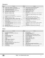
Debugging operation mode
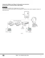
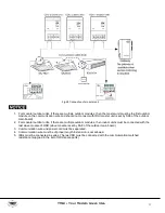
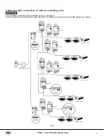
VRF multi VRF system has two debugging modes: one is direct operation on main board of outdoor units while the
other is PC operation via special software. In PC software debugging, indoor/outdoor parameters can be displayed and
historical data can be recorded and inquired. (Operation details can be found in relevant instruction manuals)
1.
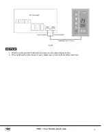
(1)Debugging through operation on main board of outdoor units
In this debugging mode, the following debugging functions are included on the main board:
Step 1:
front panel of the outdoor units must be fully closed. Open the debugging window of each basic module;
Step 2:
disconnect power for outdoor units. According to design requirements of external static pressure, set up
corresponding static pressure mode for the units. Setting methods can be seen in Outdoor Fan Static
Pressure Setup SA6_ESP_S;
Step 3:
disconnect power for outdoor units and set one module as a master unit. Setting methods can be seen in
Master Unit Setup SA8_MASTER_S;
Step 4:
Connect power for all indoor units. Make sure all IDUs are power on. Then all outdoor modules will display
“Debugging not enabled”;
Step 5:
Find the module with “01” module address to be the master module. Hold SW7 button on the master
module for at least 5s to enable debugging;
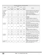
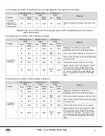
Step 6:
Wait. Unit will then start progress 01 and 02; in progress 01, if master unit is not correctly set, progress 01
will show the following errors:
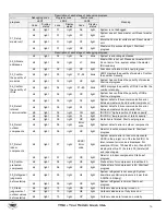
Debugging Code
Progress Code
Status Code
Meaning
Progress
LED1
LED2
LED3
Code
Display
status
Code
Display
status
Code
Display
status
01_01 Set up
master unit:
db
light
01
light
CC
light
System doesn’t have master unit. Reset master
unit.
db
light
01
light
CF
light
More than 2 master units are set. Reset master
unit.
db
light
01
light
OC
light
Master unit is successfully set. Start next
progress.
According to the above errors, reset the master unit as instructed in Master Unit Setup SA8_MASTER_S. After reset is
finished, start debugging again.
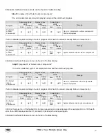
In progress 02, if master IDU is not detected, then progress 02 will show the following errors:
LED1
LED2
LED3
Function code
Display mode
Current progress
Display mode
Current status
Display mode
db
light
02
light
L7
blink
At this time, all buttons are ineffective. Set master IDU in 1min via debugging software. If master IDU is not set in 1min,
system will set up a master IDU randomly. After that, system will start next progress.
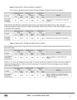
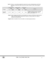
Step 7:
in progress 03, the quantity of modules needs to be confirmed manually. Main board of each module will
display:
Debugging Code
Progress Code
Status Code
Progress
LED1
LED2
LED3
Code
Display status
Code
Display status
Code
Display status
03_Quantity of modules
db
light
03
light
Quantity of
modules
blink


