27
ISOBUS Installation
– To Tractor Hitch Connector
Step 1:
Install 2940-655 Yetter ISOBUS Y Harness at Yetter Control Box. Install triangular 3 pin connector on the 2940-655 to triangular 3
pin connector on the 2940-654 Yetter Control Harness.
Step 2:
Install 2940-657 (15ft) or 2940-658 (30ft) extension harnesses to 2940-655 & route to ISOBUS connector on hitch of the tractor.
Step 3:
Install 2940-656 ISOBUS Hitch Harness to 2940-657 or 2940-658 at tractor hitch. Plug other end of 2940-656 into tractors
ISOBUS port on hitch.
ISOBUS Installation
– John Deere
Step 1:
Install the 2940-655 Yetter ISOBUS Y Harness at the Yetter Control Box. Install the triangular 3 pin connector on the
2940-655 to the triangular 3 pin connector on the 2940-654 Yetter Control Harness.
Step 2:
Remove the JD rear terminating resister harness from the planter. Install the 2940-659 JD ISOBUS Adapter Harness.
Step 3:
Install the 2940-657 (15ft) or 2940-658 (30ft) extension harnesses between the 2940-655 & 2940-659.
ISOBUS Installation
– Ag Leader (RCM I)
Step 1:
Remove terminating resister at Planter Control Module of Ag Leader system, install 2940-662 Ag Leader Adaptor harness in its place.
Step 2:
Install 2940-658 (30ft) extension harnesses between the 2940-662 & 2940-658. (2 pin connector not used, apply tape to seal off)
Step 3:
Install 2940-661 at the Yetter Control Box. Install 3 pin triangular connectors together, 6 pin Deutsch connectors install together, &
the terminating resister removed in (
Step 1
) installs to remaining open connector.
Summary of Contents for GERMINATE UNIFORMITY 2940
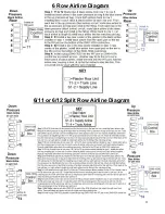
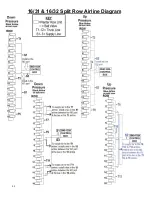
Page 35: ...35 6 Row Airline Diagram 6 11 or 6 12 Split Row Airline Diagram...
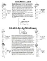
Page 36: ...36 8 Row Airline Diagram 8 15 8 16 Split Row Airline Diagram...
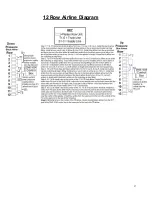
Page 37: ...37 12 Row Airline Diagram...
Page 39: ...39 16 Row Airline Diagram...
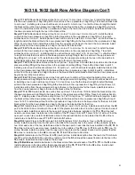
Page 40: ...40 16 31 16 32 Split Row Airline Diagram...
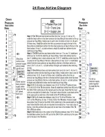
Page 42: ...42 24 Row Airline Diagram...
Page 43: ...43 24 47 24 48 Row Airline Diagram...
Page 45: ...45 32 Row Airline Diagram...
Page 46: ...46 36 Row Airline Diagram...
Page 47: ...47 48 Row Airline Diagram...
Page 48: ...48 54 Row Airline Diagram...
Page 78: ...78 HYDRAULIC PUMP 2940 545 PARTS IDENTIFICATION PART REFERENCE ONLY...
Page 82: ...82 2565 983_REV_B 09 21...

