background image


20 

***Installation Guide 

– Case IH Series Hydraulic Compressor 


STEP 1: RESIDUE MANAGER (RM) OR RM/COULTER COMBO INSTALLATION 
Residue Manager Only: 

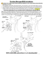
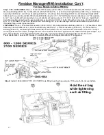
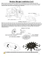
Install RM Assemblies securing with mounting hardware. Install the wheel mount assembly on the adjustment tube 

so the top hole of the wheel mount aligns to the 4

th

 or 5

th

 hole down from the top of the adjustment tube for conventional tillage/mellow soils, 

5

th

 or 6

th

 hole from the top for no till/minimum till conditions. Install wheels on wheel mounts using hardware from the 2966-119 bolt bag. 

Install the RM wheels so that the left wheel leads, right wheel trails on the left side of planter; the right wheel leads, left wheel trails on right 
side of planter.  

RM/Coulter Combo:

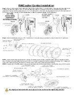
 Install the RM/Coulter Combo assembly using hardware from the 2940-128 bolt bag. Mount the coulter blade on the 

coulter arm hub & mount the RM wheels using the 5/8 Whiz Lock Nuts. RM wheels on combo units will install in the rear holes on both sides 
on all rows. It is recommended to set the coulter blade at seed depth or above. 

Refer to diagram on pages 20 

– 23 


STEP 2: TABLET/ISOBUS IN-CAB INSTALLATION  

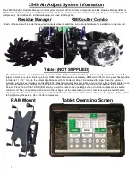
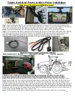
If using a tablet, mount Tablet & 2940-111 RAM Mount in tractor cab. Position Tablet within reach during operation without compromising 
safety/visibility from cab. The right rear corner post area is recommended so that the operator can see performance of residue managers 
while making adjustments. In both applications, install 2940-153A harness by feeding the bare ends thru the harness access hole into the 
cab. Bare ends get spliced to plug (not provided) that fits 

tractor’s switched power source, splice red wire on 2940-153A to orange wire & 

splice black wires together on each harness. Leave the 2 pin connector at the tractor hitch. 

Refer to diagram on page 24 


STEP 3: 2940-103A CONTROL BOX INSTALLATION 

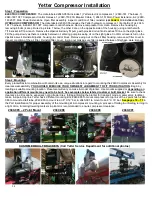
Mount control box in a safe location with mounts & hardware supplied. Mount the 2940-415 water separator/regulator assembly near control 
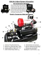
box. Locate hydraulic compressor & drain all tank pressure. Plumbing in to the compressor can happen by A) installing a 2940-408 3/8PTC 
elbow fitting in the bung on the side of tank, or B) find the 3/8 tubing that routes between the top of tank & valve manifold. Cut & install a 
Tee into that airline. Measure & cut 2940-367 250psi rated airline & route from remaining port on the Tee to inlet fitting (water trap side) of 
Yetter water separator/regulator assembly. Adjust regulator to only allow 100-120psi of clean, dry air beyond it. Measure & cut 2940-345 
black airline from outlet fitting (regulator side) of water separator/regulator assembly to inlet fitting 

of control box. Route provided ¼” airline 

from the elbow on the bottom of the water separator/regulator assembly to the ¼”PTC fitting on the bottom of control box. Route ¼” airline 
fro

m remaining ¼”PTC fitting on control box toward the ground, as this airline will dispense moisture.

 Refer to diagram on pages 25 & 32


STEP 4: CONTROL BOX HARNESS INSTALLATION)


Install 2940-166 VDM power cable with 40A breaker on tractor battery on the correct terminals, red = po, black = negative 

–. Connect 

VDM power extension (2940-167 or 2940-168) & route to tractor hitch. Install the AUX PWR Harness, 2940-164A or 2940-165A. The 2 pin 
connects to the 2940-153A from tractor cab, Anderson power connector connects to 8 gauge cable that routes to battery, & the black male 12 
pin Deutsch connector connects to power harness connector on the side of the control box. If the 2940-103A control box is mounted at the back 
of the planter, 2940-170A(10ft), 2940-171A(30ft), & 2940-430A(20ft) AUX PWR extensions will be needed. 

Refer to diagram on page 24 


ISOBUS HARNESS (IF APPLICABLE) 

Install the 2940-655 harness to 2940-654 on Yetter control box. Use 2940-657 (15ft) & 2940-658 

(30ft) extensions to reach where the ISOBUS is being tied in. On JD planters, use the 2940-659 to plug in at the back of planter where 
terminating resister harness was located. On RCM I Ag Leader systems, plug into the ISOBUS connections near the center of the planter at 
the Planter Control Module using the 2940-662 harness. On RCM II Ag Leader systems, route to tractor hitch & plug into back of tractor 
using 2940-656. 

Refer to diagram on page 26


STEP 5: PLUMBING AIRLINES 

A group of airlines that route to residue manager air bags are referred to as trunk airlines. Airline routing from  RU, RD, & WT to trunk airline is 
referred to as a supply airline. Start by routing trunk airlines: route black (down pressure) & blue (up pressure) airline on each wing/side of 
planter. Start at end row of each wing, route airline to last row on wing & install in air bag, black airline = down pressure air bag, blue airline = 
up pressure air bag. Follow airline back to end row cutting a tee in each airline at each row. When return back to end row, cut airline to length & 
install into air bag. Install airline from each tee at each row & install in air bag for that row. If installing on a split row planter, keep trunk airline 
on front rank residue managers on each wing plumbed separate from back rank. When plumbing in WT (wheel track) rows, use center 4 or 6 
rows that plant over the tractor & planter wheel tracks. If equipping on a narrow transport planter with 4 center rows & 6 rows are desired on the 
WT circuit, tie in the 1 row on each wing/side of the planter closest to the first & last center row. Install a tee in the center of each up pressure 
trunk airline. Use tees to route/install blue airline from the RU port on control box to each tee in center of each up pressure trunk airline. Install a 
tee into the down pressure trunk airline on the left wing & right wing. Route/install black airline from the RD port on control box to each tee in 
center of left & right wing down pressure trunk airline. Install tee in center of center section down pressure trunk airline. Route/install airline from 
WT port on control box to tee in the center of down pressure trunk airline on center of planter. If planter is dual rank, connect the trunk airline on 
the corn rows to the trunk airline of the bean rows. Use 2940-342 ball valves between corn row trunk airlines & bean row trunk airlines to be 
able to shut air supply off to bean rows when planting corn.  

Refer to pages 32 

– 47 


STEP 6: PERFORM A PRE-OPERATION TEST OF THE SYSTEM 

Now that the system is installed, perform a pre-operation test. Start by folding/unfolding & lowering/raising the planter checking for slack in 
airline & in harnesses at hinge points. Check all electrical connections, cables, & airline making sure nothing was damaged. Next, with the 
tractor on, connect to the WiFi with your tablet or pull the Yetter screen up on the ISOBUS VT, & press the ACTIVE SYSTEM icon. The 
compressor will turn on, build to 145psi (100-120psi on the cab controller) & shut off. Check the interior of the control box housing (valve, 
fittings, & airline) for leaks. Apply 40psi to the RU port & watch your RMs as they should all raise to maximum up travel. Check for leaks on all 
up pressure circuits & fittings. When that leak check is finished, turn RU to 0psi & turn RD & WT to 40psi. Check all down pressure airline & 
fittings in these circuits for leaks & repair as needed.  

Refer to pages 53 

– 54


Summary of Contents for GERMINATE UNIFORMITY 2940

Page 1: ...PART IDENTIFICATION 2565 983_REV_B 09 2021 Patented YETTER MANUFACTURING CO FOUNDED 1930 Colchester IL 62326 0358 Toll free 800 447 5777 309 776 3222 Fax Website www yetterco com E mail info yetterco...

Page 2: ...Regularly inspect each residue manager for loose or worn bolts hardware Repair or replace as needed All hardware used on the 2940 Air Adjust is Grade 5 unless otherwise noted Grade 5 cap screws are ma...

Page 3: ...pplementary nature The word IMPORTANT is used in the text when immediate damage will occur to the machine due to improper technique or operation Important will apply to the same information as specifi...

Page 4: ...the Company to bear cost of labor in replacement of parts It is the policy of the Company to make improvements without incurring obligations to add them to any unit already sold No warranty is made o...

Page 5: ...e implement before performing service If the machine must be serviced in the raised position jack or block it up to prevent it from accidentally falling and injuring someone Do not allow riders on the...

Page 6: ...The female port has a straight thread a machined surface minimum spot face and a chamfer to accept the O ring The seal takes place by compressing the O ring in the chamfer The threads hold the connec...

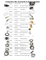
Page 7: ...raulic Hose and Fitting Kit Planter 2940 089 Hydraulic Hose and Fitting Kit Stand Alone 2940 101A Electric Compressor Unit 2940 103A Control Box for Hydraulic Compressors 2940 106 Hydraulic Compressor...

Page 8: ...40 084 kit 2940 185 Hardware Bolt Bag for 2940 085 kit 2940 186 Hardware Bolt Bag for 2940 086 kit 2940 189 10Ft Hyd Compressor Control Harness 2940 190A Pneumatic RM Assembly 2940 001A 004A 2940 192A...

Page 9: ...Elbow Fitting 1 4NPT 2940 414 3 8PTC X 1 4NPT Straight Fitting 2940 415 Water Separator Regulator Assembly 2940 416 175PSI Tank Safety Relief Valve 2940 430A 20 ft Aux to Air Harness Extension 2940 43...

Page 10: ...d Regulator fittings not included 2940 646 NPT Street Elbow 2940 647 NTP to 5 32 Run Tee 2940 648 NPT Bulkhead 2940 649 NPT to 3 8 Run Tee 2940 650 NPT to Tube PTC Elbow Fitting 2940 651 5 32 Tubing 2...

Page 11: ...protect the motor seals from thermal expansion Plumb the case drain so that hydraulic oil returns to the same reservoir used for the pressure and return If the tractor is not equipped with a female fl...

Page 12: ...ger RAM Tablet Mount will be necessary RAM HOL UN11U can be purchased online for tablets 11 12 Go into the tablets App Store search for Yetter Air Adjust download the App Once the system is installed...

Page 13: ...i Other pneumatic systems for example pneumatic down force or air clutches can be plumbed using the Yetter compressor as its air source Be sure to regulate the air entering any other systems to OEM sp...

Page 14: ...t 6 ORFS 1 J 2940 546 Hydraulic Compressor Control Block 1 K N A Flow Control Valve 1 L 2940 544 Hydraulic Pressure Gauge 1 M 2940 506 2940 543 Hydraulic On Off Valve COIL ONLY Hydraulic On Off Cartri...

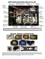
Page 15: ...Combo on the planter WATER SEPARATOR INLET Install the airline from the bottom of the water separator into this port WATER SEPARATOR OUTLET Install airline in this port route toward the ground drain...

Page 16: ...sed for every cut to ensure a clean square cut is made 2940 441A PRESSURE TRANSDUCER 1 per circuit 2940 637 VALVE ASSEMBLY 2940 112A MIDAC MODULE MOUNTED TO BACK WALL INTERIOR HARNESS NO PART 2940 441...

Page 17: ...er extension 2940 167 or 2940 168 route to the tractor hitch Install the AUX PWR Harness 2940 164A or 2940 165A The 2 pin connects to the 2940 153A from the tractor cab the Anderson power connector co...

Page 18: ...all the AUX PWR Harness 2940 164A or 2940 165A The 2 pin connects to the 2940 153A from tractor cab Anderson power connector connects to 8 gauge cable that routes to battery the black male 12 pin Deut...

Page 19: ...0 170A 10ft 2940 171A 30ft 2940 430A 20ft AUX PWR extensions will be needed Refer to diagram on page 24 ISOBUS HARNESS IF APPLICABLE Install the 2940 655 harness to 2940 654 on Yetter control box Use...

Page 20: ...A control box is mounted at the back of the planter 2940 170A 10ft 2940 171A 30ft 2940 430A 20ft AUX PWR extensions will be needed Refer to diagram on page 24 ISOBUS HARNESS IF APPLICABLE Install the...

Page 21: ...blades a 2940 049 kit will need installed to space the RM or RM Coulter Combo mounting bracket assembly out to avoid interference See page 60 For Harvest International Horsch John Deere Kinze White Mo...

Page 22: ...nuts Note direction of mounting bolt Cyclo stop castings can also be mounted to square hole on the upstop flange under top parallel arms 2100 SERIES Place 1 Pneumatic RM Assembly 2940 190A 1 Mounting...

Page 23: ...mount using 2 5 8 lock washers 2 5 8 hex nut Mount the wheels so the left side of the planter has the left wheel leading right wheel trailing Mount the wheels so that right side of the planter has th...

Page 24: ...nsion Step 2 Install coulter blade using 4 X1 bolts 4 lock nuts using a socket wrench impact 10 extension NOTE Adjust coulter blade depth equal to or above the planter opener blades Adjust the blade d...

Page 25: ...AT P N AG233356 FAILURE TO LINE UP TABS WHEN PLUGGING MALE INTO FEMALE CONNECTORS CAN RESULT IN SHORT CIRCUIT ALSO CHECK TAB SLOT SIZES PLUGGING CONNECTORS IN BACKWARDS WILL RESULT IN A FAULTY SYSTEM...

Page 26: ...l by compressor 2940 084 handrail between bulk fill tanks See page 72 for diagram of the 2940 084 Once the 2940 103A Control Box is mounted install the Aux Extension black 12 pin Deutsch that routes f...

Page 27: ...lar 3 pin connector on the 2940 655 to the triangular 3 pin connector on the 2940 654 Yetter Control Harness Step 2 Remove the JD rear terminating resister harness from the planter Install the 2940 65...

Page 28: ...ct condition of the air filter Reinstall filter cover wing nut making sure filter is sealed between filter base plate cover Step 2 Mounting Every planter tractor combination will contain its own uniqu...

Page 29: ...hased 2940 088 PLANTER 2940 089 kit STAND ALONE Part Part Name Description Qty in kit Qty in kit 4 2 2515 324 ELBOW 90 DEG 3 4 SAE TO 6 JIC 2 2515 327 ADAPTER 3 4 16 SAE TO 6 JIC 3 2515 329 ADAPTER RE...

Page 30: ...ed with threaded plug may also have rubber plug install the 2515 848 4 ORB to 6 JIC 90 degree adaptor fitting so that the O Ring end goes into the hydraulic motor the JIC end faces downward Install 1...

Page 31: ...teeing into the lift lower bulk fill fan on a John Deere planter plumb the Yetter hydraulic compressors pressure circuit into the planter s return circuit usually labeled V2A on the hydraulic block pl...

Page 32: ...is needed call Yetter order more 2940 182 is 20ft length 2940 189 is 10ft length Step 3 Connect the 2940 182 or 2940 189 into the 4 pin female connector on side of the control box John Deere Hydraulic...

Page 33: ...ifold as indicated by arrow or by installing a 2940 408 in bung on side of compressor tank Step 2 Route 2940 367 250psi rated 3 8 airline from the installed Tee to the inlet labeled A of the Yetter wa...

Page 34: ...air bag RM Coulter Combo models will have 2 air bags on the bottom of the bracket for up pressure a single air bag on top is for down pressure The 2 up pressure air bags will have airline connected to...

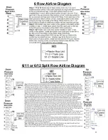
Page 35: ...35 6 Row Airline Diagram 6 11 or 6 12 Split Row Airline Diagram...

Page 36: ...36 8 Row Airline Diagram 8 15 8 16 Split Row Airline Diagram...

Page 37: ...37 12 Row Airline Diagram...

Page 38: ...air bag fitting Trace both airlines back to split 4 installing a tee in each airline at split rows 5 7 At split row 4 cut both airlines to length install the black airline in the down pressure air bag...

Page 39: ...39 16 Row Airline Diagram...

Page 40: ...40 16 31 16 32 Split Row Airline Diagram...

Page 41: ...bag fitting Trace both airlines back to split 6 installing a tee in each airline at split rows 7 9 At split row 6 cut both airlines to length install the black airline in the down pressure air bag fi...

Page 42: ...42 24 Row Airline Diagram...

Page 43: ...43 24 47 24 48 Row Airline Diagram...

Page 44: ...g fitting Trace both airlines back to split 9 installing a tee in each airline at split rows 10 13 At split row 9 cut both airlines to length install the black airline in the down pressure air bag fit...

Page 45: ...45 32 Row Airline Diagram...

Page 46: ...46 36 Row Airline Diagram...

Page 47: ...47 48 Row Airline Diagram...

Page 48: ...48 54 Row Airline Diagram...

Page 49: ...u can change the name of the preset or the psi that the preset is currently saved as The preset that is being used will be highlighted in GREEN the name of the preset will be shown If the operator has...

Page 50: ...essing FACTORY RESET will change all presets back to factory settings SYSTEM INFO On the system info screen the operator can select 5 different icons or press BACK to go back to the MENU screen or EXI...

Page 51: ...e 2 modules to make sure nothing became disconnected damaged Operation Settings How much Down Lift Pressure should I be running The amount of Down Lift Pressure will vary greatly across soil types til...

Page 52: ...crop residue to break up clods crust 2 DO NOT operate planter at slow speeds Ground speed affects how aggressive the residue manager wheels are Operate at sufficient speed refer to you OEM planter man...

Page 53: ...arms are level fore aft Re Check when the planter is in the field has been fully loaded with seed fertilizer etc Also a field check with a bubble level on the frame should be made of the hitch height...

Page 54: ...nut by turning wrench counterclockwise STEP 4 Using the Allen wrench SLIGHTLY turn the flow control valve counterclockwise the equivalent to 3 degrees or 1 32 of a turn to increase the hydraulic moto...

Page 55: ...sn t remove enough residue or trenches digs furrows adjust the settings accordingly until the row cleaner is doing exactly what you want it to do If the row cleaner is trenching move to a lighter pres...

Page 56: ...in Valve 10 seconds see illustration to the right to allow moisture to drain SEASONALLY 200 COMPRESSOR HOURS Change compressor oil Change inlet air filter Check fluid hoses and air lines for weakness...

Page 57: ...used clean dirt debris from inside of box inspect all parts for damage leaks replace as needed Maintenance Lubrication Symbols Lubricate with grease at hourly interval indicated on symbol Lubrication...

Page 58: ...N 2940 049A For John Deere Planters with Heavy Duty Double Disc Scrapers Item Part Number Description Qty 1 2502 294 1 2 13 x 1 1 2 HHCS GR 5 ZP 3 2 2520 357 13 HEX LOCK NUT ZP 3 3 2526 355 FLAT WASHE...

Page 59: ...ATCH LOC GR 5 2 7 2520 601 3 8 16 HEX TOP LOCK GR C ZP 7 8 2526 201 5 16 STANDARD FLAT WASHER 2 9 2940 210 ADJUSTMENT TUBE 1 10 2940 211A UPPER LINK W A 1 11 2940 213 LOWER PARALLEL 1 12 2940 214 AIR...

Page 60: ...ATCH LOC GR 5 2 7 2520 601 3 8 16 HEX TOP LOCK GR C ZP 7 8 2526 201 5 16 STANDARD FLAT WASHER 2 9 2940 210 ADJUSTMENT TUBE 1 10 2940 211A UPPER LINK W A 1 11 2940 213 LOWER PARALLEL 1 12 2940 214 AIR...

Page 61: ...3 D BOLT 1 2966 140 BW FW BEVEL WHEEL ASSEMBLY RH 3 D BOLT WITH FLOATER WHEEL 1 2966 140 FW SPOKE WHEEL ASSEMBLY RH 3 D BOLT WITH FLOATER WHEEL 1 2966 140 HD HD SPOKE WHEEL ASSEMBLY RH 3 D BOLT 1 296...

Page 62: ...3 8 PC X 1 8 BSPP O RING STRAIGHT FITTING 2 17 2960 411 CYCLO STOP CASTING LARGE HOLE 2 18 2966 140 2966 140 BW 2966 140 BW FW 2966 140 FW 2966 140 HD 2966 140 HD FW 2966 140 ST 2966 140 ST FW SPOKE...

Page 63: ...HEEL ASSEMBLY RH 3 D BOLT WITH FLOATER WHEEL 1 2966 140 FW SPOKE WHEEL ASSEMBLY RH 3 D BOLT WITH FLOATER WHEEL 1 2966 140 HD HD SPOKE WHEEL ASSEMBLY RH 3 D BOLT 1 2966 140 HD FW HD SPOKE WHEEL ASSEMBL...

Page 64: ...121 ASSEMBLY COULTER HUB 1 12 2940 230 FACEPLATE W A JD 1700 7200 AGCO 9000 1 13 2940 231 COMBO ARM W A 1 14 2940 381 3 8 PC X 1 8 BSPP O RING 90 DEGREE 2 15 2940 383 3 8 PC WYE FITTING 1 16 2940 386...

Page 65: ...ZP 1 11 2940 121 ASSEMBLY COULTER HUB 1 12 2940 231 COMBO ARM W A 1 13 2940 232 FACEPLATE W A 1 14 2940 381 3 8 PC X 1 8 BSPP O RING 90 DEGREE 2 15 2940 383 3 8 PC WYE FITTING 1 16 2940 386 SHORTER A...

Page 66: ...WASHER HARDENED ZP 3 8 2940 130A PNEUMATIC COMBO SUBASSEMBLY FOR JD 1700 7200 AGCO 9000 1 9 2966 116 FW SPOKE WHEEL ASSEMBLY RH 2 3 4 D BOLT WITH FLOATER WHEEL 1 2966 116 ST FW SHARK TOOTH WHEEL ASSEM...

Page 67: ...R 2 ZP 2 7 2526 355 FLAT WASHER HARDENED ZP 3 8 2940 126A PNEUMATIC COMBO SUBASSEMBLY 1 9 2966 116 FW SPOKE WHEEL ASSEMBLY RH 2 3 4 D BOLT WITH FLOATER WHEEL 1 2966 116 ST FW SHARK TOOTH WHEEL ASSEMBL...

Page 68: ...68 PARTS IDENTIFICATION 2966 140 ST FW RIGHT HAND SHARK TOOTH WHEEL ASSEMBLY 2966 140 ST FW LEFT HAND SHARK TOOTH WHEEL ASSEMBLY...

Page 69: ...69 PARTS IDENTIFICATION 2966 140 FW RIGHT HAND TAPER TOOTH WHEEL ASSEMBLY 2966 141 FW LEFT HAND TAPER TOOTH WHEEL ASSEMBLY...

Page 70: ...70 PARTS IDENTIFICATION 2966 140 BW FW RIGHT HAND BEVEL WHEEL ASSEMBLY 2966 141 BW FW LEFTT HAND BEVEL WHEEL ASSEMBLY...

Page 71: ...OTH 2966 116 FW TAPER TOOTH WHEEL Item Part Number Description Qty 1 2502 220 5 16 18 X HHFS 4 2 2502 222 5 16 18 X 1 1 4 HHFS 4 3 2570 994 PLUG BEVEL WHEEL ONLY 1 4 2571 287 L 13 BEVEL WHEEL 8 BOLT L...

Page 72: ...162 YETTER DECAL 1 X 4 1 2 2940 121 ASSEMBLY COULTER HUB 1 3 2940 232 FACEPLATE W A JD 7000 AGCO 6000 8000 KINZE 1 Item Part Number Description Qty 1 2565 162 YETTER DECAL 1 X 4 1 2 2940 121 ASSEMBLY...

Page 73: ...P 1 9 2550 027 D CONE LM67010 KOYO 2 10 2550 029 D CUP LM67010 KOYO 2 11 2940 578 COULTER SPINDLE 1 12 2940 579 MACHINED HUB CASTING 1 13 6010 440 HUB CAP BLACK Item Part Number Description Qty 1 2502...

Page 74: ...4 4 2520 459 5 8 11 LOCK HEX NUT ZP 2 5 2940 479 ANGLE MOUNT BRACKET 2 Item Part Number Description Qty 1 2502 198 5 16 18 X 1 HHCS GR 5 ZP 7 2 2502 207 5 16 18 X 2 HHCS GR 5 ZP 4 2502 212 5 16 18 X...

Page 75: ...5 ZP 4 2 2502 373 13 X 6 HHCS GR 5 ZP 4 3 2520 352 13 HEX NUT ZP 4 4 2520 357 13 LOCK HEX NUT ZP 4 5 2525 352 MED LOCK WASHER ZP 4 6 2526 352 SAE FLAT WASHER ZP 8 7 2940 207 COMPRESSOR MOUNT W A LH 1...

Page 76: ...ESSOR STRAP 2 7 2940 351 COMPRESSOR MOUNT BRACKET 4 Item Part Number Description Qty 1 2502 294 13 X 1 HHCS GR 5 ZP 4 2 2502 388 5 8 11 X 14 HHCS GR 5 ZP IN THE 2940 090 KIT 4 2502 389 5 8 11 X 18 HHC...

Page 77: ...A MOTOR ELBOW FITTING 1 12 N A INLET ELBOW FITTING 1 13 2940 519A HYDRAULIC COMPRESSOR FAN CAST will fit on all Yetter Hyd Compressors 1 14 2940 549 HYDRAULIC COMPRESSOR AIR FILTER FILTER ELEMENT ONLY...

Page 78: ...78 HYDRAULIC PUMP 2940 545 PARTS IDENTIFICATION PART REFERENCE ONLY...

Page 79: ...2940 638 INLET ASSEMBLY 1 2940 639 POR ASSEMBLY 3 2940 640 MAC BV VLAVE 2 WAY 6 2940 641 10 32 TO TUBE BARB FITTING 3 2940 642 10 32 TO TUBE PTC FITTING 3 2940 643 TUBE ORIFICE 3 2940 644 NPT TEE 4 29...

Page 80: ...1 8NPT ELBOW 6 2940 377 COMPRESSOR PRESSURE SWITCH 125 145PSI 1 7 2940 395 FILTER ELEMENT 1 8 2940 390 ELECTRIC COMPRESSOR 1 9 2940 391 COMPRESSOR RELAY 1 10 N A 12 GALLON TANK 1 11 N A 1 4 TURN TANK...

Page 81: ...mmunication harness connection issue 1 press ACTIVATE SYSTEM 2 check power connections from battery to VDM check 2940 166 breaker at the battery 3 allow the compressor to build at least 75psi 4 replac...

Page 82: ...82 2565 983_REV_B 09 21...

Reviews: