2
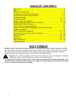
TABLE OF CONTENTS
Bolt Torque……………………………………………………………………….......2
Safe
ty……………………………………………………………………………........4
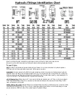
Hydraulic Fitting
s Chart…………………………………………………………......5
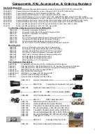
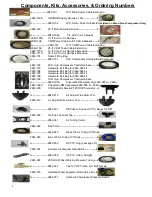
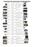
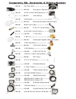
Components, Kits, an
d Part Numbers………………....……………………...6 – 9
Introduction & System Requirements.........................
……………………….…10
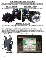
System Information..................................................................................11
– 15
Installation Guide….……………………………………………………….....16 – 19
Residue Manager Installation................................................
....…...........20 – 22
Residue Manager/Coulter Combo Installation………………………………......23
Tablet Mount / Power Harness ................................
........……….........…...….24
2940-103A Control Box In
stallation………………………………….……..........25
2940-
415 Water Separator/Regulator Assembly Installation………................25
ISOBUS Installation.........................................................................................26
Yetter Compressor
Installation…................………….......……....….........27 – 30
Compressor to Control Box
Airline Installation…………………………….31 – 32
Airline Installation.....................................................................................32
– 47
Operatio
n………………………………………………………………………48 – 54
Maintena
nce………………………………………………………………......55 – 56
Parts Identificati
on…………………………………………………...............57 – 78
Troubleshooting..............................................................................................
79
BOLT TORQUE
Regularly inspect each residue manager for loose or worn bolts & hardware. Repair or replace as needed.
All hardware used on the 2940 Air Adjust is Grade 5 unless otherwise noted. Grade 5 cap screws are marked with
three radial lines on the head. If hardware must be replaced, be sure to replace it with hardware of equal size,
strength and thread type. Refer to the torque values chart when tightening hardware.
Important:
Over tightening hardware can cause as much damage as when under tightening. Tightening
hardware beyond the recommended range can reduce its shock load capacity.
The chart below is a guide for proper torque. Use it unless a specified torque is called out elsewhere in the
manual. Torque is the force you apply to the wrench handle or the cheater bar, times the length of the handle
or bar. Use a torque wrench whenever possible.
Summary of Contents for GERMINATE UNIFORMITY 2940
Page 35: ...35 6 Row Airline Diagram 6 11 or 6 12 Split Row Airline Diagram...
Page 36: ...36 8 Row Airline Diagram 8 15 8 16 Split Row Airline Diagram...
Page 37: ...37 12 Row Airline Diagram...
Page 39: ...39 16 Row Airline Diagram...
Page 40: ...40 16 31 16 32 Split Row Airline Diagram...
Page 42: ...42 24 Row Airline Diagram...
Page 43: ...43 24 47 24 48 Row Airline Diagram...
Page 45: ...45 32 Row Airline Diagram...
Page 46: ...46 36 Row Airline Diagram...
Page 47: ...47 48 Row Airline Diagram...
Page 48: ...48 54 Row Airline Diagram...
Page 78: ...78 HYDRAULIC PUMP 2940 545 PARTS IDENTIFICATION PART REFERENCE ONLY...
Page 82: ...82 2565 983_REV_B 09 21...

