38
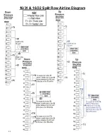
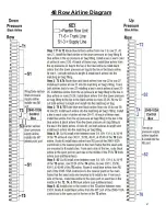
12/23 & 12/24 Split Row Airline Diagram
Step 1: T1 & T2
Route black & blue airline from corn row 1 to corn row 4. At corn row 4, install the black airline into the down pressure air bag fitting & the blue
airline in the up pressure air bag fitting. Trace both airlines back to corn row 1, installing a tee in each airline at corn rows 2 & 3. At corn row 1, cut both airlines to
length & install the black airline in the down pressure air bag fitting & the blue airline in the up pressure air bag fitting. At corn rows 2 & 3, install blue airline from
the up pressure air bag to the tee in the blue airline & install black airline from the down pressure air bag to the tee in the black airline.
Step 2: T3 & T4
Route black & blue airline from corn row 5 to corn row 8. At corn row 8, install the black airline into the down pressure air bag fitting & the blue
airline in the up pressure air bag fitting. Trace both airlines back to corn row 5, installing a tee in each airline at corn rows 6 & 7. At corn row 5, cut both airlines to
length & install the black airline in the down pressure air bag fitting & the blue airline in the up pressure air bag fitting. At corn rows 6 & 7, install blue airline from
the up pressure air bag to the tee in the blue airline & install black airline from the down pressure air bag to the tee in the black airline.
Step 3: T5 & T6
Route black & blue airline from corn row 9 to corn row 12. At corn row 12, install the black airline into the down pressure air bag fitting & the blue
airline in the up pressure air bag fitting. Trace both airlines back to corn row 9, installing a tee in each airline at corn rows 10 & 11. At corn row 9, cut both airlines
to length & install the black airline in the down pressure air bag fitting & the blue airline in the up pressure air bag fitting. At corn rows 10 & 11, install blue airline
from the up pressure air bag to the tee in the blue airline & install black airline from the down pressure air bag to the tee in the black airline.
Step 4: T7 & T8
Route black & blue airline from split row 1 to split row 3 & install the black airline into the down pressure air bag fitting & the blue airline in the up
pressure air bag fitting. Trace both airlines back to split 1, installing a tee in each airline at split row 2. At split row 1, cut both airlines to length & install the black
airline in the down pressure air bag fitting & the blue airline in the up pressure air bag. At split row 2, install blue airline from the up pressure air bag to the tee in
the blue airline & install black airline from the down pressure air bag to the tee in the black airline.
Step 5: T9 & T10
Route black & blue airline from split row 4 to split row 8 & install the black airline into the down pressure air bag fitting & the blue airline in the
up pressure air bag fitting. Trace both airlines back to split 4, installing a tee in each airline at split rows 5-7. At split row 4, cut both airlines to length & install the
black airline in the down pressure air bag fitting & the blue airline in the up pressure air bag fitting. At split rows 5-7, install blue airline from the up pressure air
bag to the tee in the blue airline for that row & install black airline from the down pressure air bag to the tee in the black airline for that row.
Step 6: T11 & T12
Route black & blue airline from split row 9 to split row 11/12 & install the black airline into the down pressure air bag fitting & the blue airline in
the up pressure air bag fitting. Trace both airlines back to split 9, installing a tee in each airline at split rows 10 or 10 &11. At split row 9, cut both airlines to length
& install the black airline in the down pressure air bag fitting & the blue airline in the up pressure air bag fitting. At split rows 10 or 10 & 11, install blue airline from
the up pressure air bag to the tee in the blue airline for that row & install black airline from the down pressure air bag to the tee in the black airline for that row.
Step 7: S1
Install a tee in the middle of the
T1
&
T5
airline. From the open port on each tee, route & install black airline to the center of the planter & connect the
two airlines using a tee. From the open port on this tee, route & install black airline to the RD port on the 2940-103A control box. Install a tee in the middle of the
T7
&
T11
airline. From the open port on each tee, route & install black airline to the nearest location on the planter that the
S1
airline is. Install a tee in the
S1
to
connect
T7
&
T11
airline to
S1
airline.
Step 8: S2
Install a tee in the middle of the
T2
,
T4
, &
T6
airline. Route & install blue airline from the open port of the tee in the
T2
&
T6
airline to the center of the
planter & connect the two airlines using a tee. Install blue airline from the open port on the tee to the tee in the
T4
airline. Cut & install another tee next to the tee
that connects the
T2
,
T4
, &
T6
airline. Install blue airline between the open port on this tee to the RU port on the 2940-103A control box. Install a tee in the middle
of the
T8
,
T10
, &
T12
airline. Route & install blue airline from the open port of each tee to the nearest location on the planter that the
S2
airline is. Install a tee in
the
S2
to connect
T8
,
T10
, &
T12
airline.
Step 9: S3
Install a tee in the
T3
&
T9
airline. Install black airline from the tee in the
T3
airline to the WT port on the 2940-103A control box. Install a tee in the
S3
airline at the nearest location to the tee in the
T9
airline & install black airline between the two tees.
Step 10 Ball Valves
Install a ball valve in the black airline that connects each of the
T7
&
T11
to the
S1
airline. Install a ball valve in the blue airline that connects
each of the
T8
,
T10
, &
T12
to the
S2
airline. Install a ball valve in the black airline that connects the
T9
to the
S1
airline.
Summary of Contents for GERMINATE UNIFORMITY 2940
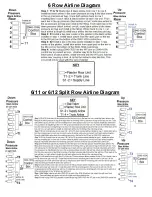
Page 35: ...35 6 Row Airline Diagram 6 11 or 6 12 Split Row Airline Diagram...
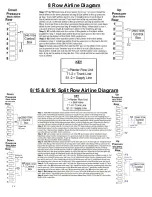
Page 36: ...36 8 Row Airline Diagram 8 15 8 16 Split Row Airline Diagram...
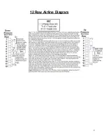
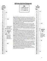
Page 37: ...37 12 Row Airline Diagram...
Page 39: ...39 16 Row Airline Diagram...
Page 40: ...40 16 31 16 32 Split Row Airline Diagram...
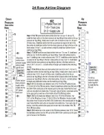
Page 42: ...42 24 Row Airline Diagram...
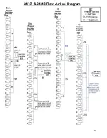
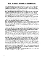
Page 43: ...43 24 47 24 48 Row Airline Diagram...
Page 45: ...45 32 Row Airline Diagram...
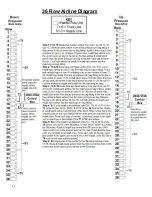
Page 46: ...46 36 Row Airline Diagram...
Page 47: ...47 48 Row Airline Diagram...
Page 48: ...48 54 Row Airline Diagram...
Page 78: ...78 HYDRAULIC PUMP 2940 545 PARTS IDENTIFICATION PART REFERENCE ONLY...
Page 82: ...82 2565 983_REV_B 09 21...

