background image

Short Form Installation Guide  

Appendix A 

42 

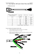
9.5.  Connecting Pulse A/B Encoder without C Pulse (Index Pulse) 


OEM Encoder Cable 


XtraDrive Side Pin Number 

(20-pin connector) 

Signal Name 

Wire Color 

Remarks 

1,2,3 PG 

GND 

Black 

--- 

Red  

4,5,6 PG 

+5V 

White 

Twisted 

Pair 

14 PC 

Green 

15 /PC 

White 

Twisted 

Pair 

16 PA 

Blue 

17 /PA 

White 

Twisted 

Pair 

18 PB 

Yellow 

19 /PB 

White 

Twisted 

Pair 

FG Connector 

Shield 

Yellow/Green 

--- 


In case of using an A/B encoder without C pulse: 

• 

Connect signal PC (Green Wire) directly to +5V terminal  

(together with Red-White PG +5V wires)  

• 

Connect signal /PC (White wire from Green-White pair) directly to GND 
terminal (together with Black wire) 


Summary of Contents for XtraDrive XD Series

Page 1: ...XtraDrive XD SERIES AC SERVO DRIVER Prior to installing the product read these instructions thoroughly and retain for future reference Short Form Installation Guide Catalog No 8U0107...

Page 2: ...Short Form Installation Guide Introduction 2...

Page 3: ...n made to make this guide complete and as accurate as possible However no warranty of suitability purpose or fitness is made or implied YET Ltd is not liable or responsible to any person or entity for...

Page 4: ...XtraDrive 23 4 2 5 Three phase 200V Main Circuit 24 4 2 6 Example of Connections for Three phase 200V XtraDrive 25 4 2 7 Three phase 400V Main Circuit 26 4 2 8 Example of Connections for Three phase...

Page 5: ...ies 37 8 2 Noise Filter for Brake Power Supply 38 8 3 Cable Specifications 38 8 4 Recommended Ferrite Cores 38 8 5 Shield Box 38 9 Appendix A 39 9 1 I O Signals Connector CN1 39 9 2 Encoder Connector...

Page 6: ...AC Servo Motor Instructions for Yaskawa II series motors or documentation for other compatible motors TOE C231 2 for II Manufacturer s motor specification XtraWare User s Manual 8U0109 Topics describ...

Page 7: ...of the XtraDrive Servo Drives WARNING Installation After voltage resistance test wait at least five minutes before servicing the product Failure to observe this warning could result in electric shock...

Page 8: ...materials rated for 400V and keep the wires as short as possible 17 17 17 Operation To avoid accidents perform a test run of the servomotor with no load Failure to observe this caution could result i...

Page 9: ...Short Form Installation Guide Introduction 9 1 2 Warning Label...

Page 10: ...Short Form Installation Guide Introduction 10 1 3 Parts The part names of the XtraDrive series AC Servo Driver are shown in the following diagram...

Page 11: ...the delivered products the ones you ordered Check the types marked on the nameplates of the servomotor and XtraDrive Does the motor shaft rotate smoothly The motor shaft should rotate smoothly when ro...

Page 12: ...put Voltage M 200VAC or T 400VAC Extended Functionality By Option Boards S no CN10 connector or N with CN10 connector Design Version Blank or 01 FF optional Blank or R Rack mounted or V Board coating...

Page 13: ...N55011 1198 Group 1 Class A EN61000 6 2 1999 3 3 Installation Locations Different locations for the XtraDrive necessitate certain conditions as described in the following table Installation Location N...

Page 14: ...lation 14 3 4 Orientation Install the XtraDrive perpendicular to the wall and orientate it as shown in the figure below Firmly secure the XtraDrive through two or four mounting holes depending on the...

Page 15: ...all XtraDrive perpendicular to the wall so that the front panel digital operator mounted face faces outward Cooling Provide sufficient space around each XtraDrive to allow cooling by fan and natural c...

Page 16: ...owing conditions inside the control box Ambient temperature for XtraDrive 0 to 55 C Humidity 90 RH or less no condensing Vibration 4 9 m s2 No freezing Ambient temperature to ensure long term reliabil...

Page 17: ...aDrive the amount of current leaking from the power line increases Therefore use cables and isolation materials rated for 400V and keep the wires as short as possible Refer to the XtraDrive s Design a...

Page 18: ...Max 16 mm 0 63 in for CN1 and max 6 8 mm 0 27 in for CN2 For 200 V Offline terminals Ground terminal AWG14 HIV 2 0 0 003 min Wire Size mm2 in2 External Terminal Name 05 08 10 15 20 30 Main circuit po...

Page 19: ...rent Connector Name and Signal Item Specification Cable Twisted pair or shielded twisted pair wire Applicable wire AWG24 0 2 mm2 0 0003 in2 AWG26 0 12 mm2 0 0002 in2 AWG28 0 08 mm2 0 0001 in2 AWG30 0...

Page 20: ...Short Form Installation Guide Wiring 20 4 2 Connecting to Peripheral Devices 4 2 1 Single phase 200V Main Circuit...

Page 21: ...s 2 The time constant for the primary filter is 47us 6 These circuits are SELV circuits therefore are separated from all other circuits by double and reinforced insulator 3 Connect only with an absolu...

Page 22: ...main power supply shown below to L1 and L3 terminals Power supply is single phase 220 to 230 VAC 10 to 15 50 60Hz If power supply of 187V 15 of 220V or less is used alarm A 41 indicating voltage shor...

Page 23: ...LV circuits therefore are separated from all other circuits by double and reinforced insulator 3 Connect only with an absolute encoder 7 Use a double insulated 24 VDC power supply 4 Used only with an...

Page 24: ...Short Form Installation Guide Wiring 24 4 2 5 Three phase 200V Main Circuit...

Page 25: ...fore are separated from all other circuits by double and reinforced insulator 4 Used only with an absolute encoder 8 Use a double insulated 24 VDC power supply 9 Optional not available in all models 5...

Page 26: ...Short Form Installation Guide Wiring 26 4 2 7 Three phase 400V Main Circuit...

Page 27: ...fore are separated from all other circuits by double and reinforced insulator 4 Used only with an absolute encoder 8 Use a double insulated 24 VDC power supply 9 Optional not available in all models 5...

Page 28: ...of the XtraDrive Never share the grounding cable or main grounding point with welding equipment power equipment or other high voltage devices Separate the grounding cable from wiring of high voltage...

Page 29: ...n a power supply of 187V 15 of 220V or less is used alarm A41 indicating voltage shortage may occur when accelerating to max speed with max torque of servomotor 4 4 DC Power Source Supply 3 Phase 400V...

Page 30: ...ant Pn100 to 40 or less The factory setting is 40 The speed loop gain user constant Pn100 is determined by Load inertia servomotor inertia 1 to 3 Therefore if the servomotor is rotated without a load...

Page 31: ...ailure to observe this warning could result in electric shock After turning OFF power wait at least five minutes before servicing the product Otherwise residual electric charges could result in electr...

Page 32: ...tems using an absolute encoder When battery voltage is 2 7V or less XtraDrive outputs absolute encoder battery alarm A 83 when using Yaskawa II motors with absolute encoder only when the XtraDrive pow...

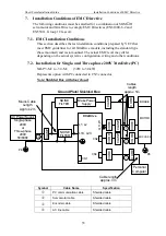
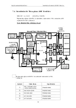
Page 33: ...tem s configuration wiring and other conditions 7 2 Installation for Single and Three phase 200V XtraDrive PC XD P3 M to 30 M 30W to 3 0kW Represents option with PC connected to CN3 connector Note Shi...

Page 34: ...ke Power Supply CLAMP CLAMP AC Power Supply Single phase 200V or Three phase 200V 50 60Hz U V W L1 L2 L1C L2C CLAMP CLAMP CORE CORE CORE CORE CORE BRAKE MOTOR ENCODER PE PLC or Controller PE CN3 CN1 C...

Page 35: ...LAMP CORE CORE CORE CORE CORE BRAKE MOTOR ENCODER PE PE CN3 CN1 CN2 Ground Plate Shielded Box Cable length approx 3m XtraDrive Mains Cable Length Approx 2m Cables length approx 5m PLC or Controller CO...

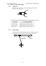
Page 36: ...e below lists the cable names and the mounting positions of the core Cable Name Core Mounting Position Controller cable Near the Controller and the XtraDrive Servomotor cable Near the XtraDrive and th...

Page 37: ...A 2 1 11 Fn2070 16 07 Single phase 250 VAC 16 A 35 SGMGH 09A A SGMGH 09A B 1 0 10 M SGMSH 10A 2 3 7 SGMGH 20A A SGMGH 20A A 2 0 20 M SGMSH 20A 4 3 13 Fn258L 16 07 Three phase 480VAC 16A 35 SGMDH 22A S...

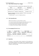
Page 38: ...the following cables AC power input line cable between power supply and noise filter Servomotor cable between XtraDrive and Servomotor Encoder cable between XtraDrive and Servomotor Controller cable b...

Page 39: ...o Terminal Layout Pin No Name Pin No Name 1 Signal Ground 26 V CMP out 1 2 Signal Ground 27 TGON out 2 3 PL1 28 TGON out 2 4 SEN 29 S RDY out 3 5 V REF 30 S RDY out 3 6 Signal Ground 31 ALM out 4 7 PU...

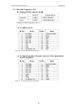
Page 40: ...PG GND 2 PG GND 12 BAT 3 PG GND 13 BAT 4 PG 5V 14 PC 5 PG 5V 15 PC 6 PG 5V 16 PA 7 NC 17 PA 8 PS 18 PB 9 PS 19 PB 10 Serial PG 5V 20 NC Note NC Leave contact open Not Connected Terminal Layout for Enc...

Page 41: ...TXD 3 RXD 10 RXD 4 RXD 11 NC 5 NC 12 NC 6 RXD 13 5V 7 RT termination resistor 14 GND Note NC Leave contact open Not Connected 9 4 Analog Monitor Connector CN5 Mating 4 Pin Connector Model YET P N Mode...

Page 42: ...Red 4 5 6 PG 5V White Twisted Pair 14 PC Green 15 PC White Twisted Pair 16 PA Blue 17 PA White Twisted Pair 18 PB Yellow 19 PB White Twisted Pair FG Connector Shield Yellow Green In case of using an A...

Page 43: ...ayin 48091 Statesboro GA 30458 ISRAEL USA Tel 972 3 9004114 Tel 1 912 871 7691 Fax 972 3 9030412 Fax 1 912 531 7691 info yetmotion com trincon yetmotion com For more information refer to our web site...

Reviews: