yellow jacket 40870 User Manual Download Page 20

17 


During the pressure decay test, Pc will adjust as the current system pressure changes. Pi-Pc will 

adjust to reflect the change between the initial system pressure and current system pressure. 

Limit will display the limit pressure as determined by the percent allowable change. System 

pressure dropping below this value within the time limit as set by the test duration will trigger a 

failure. The rate of change as denoted by %/min displays the percent change in system pressure 

per minute. A large leak will be indicated by a larger %/min value, conversely a smaller %/min 

indicates a small system leak. 


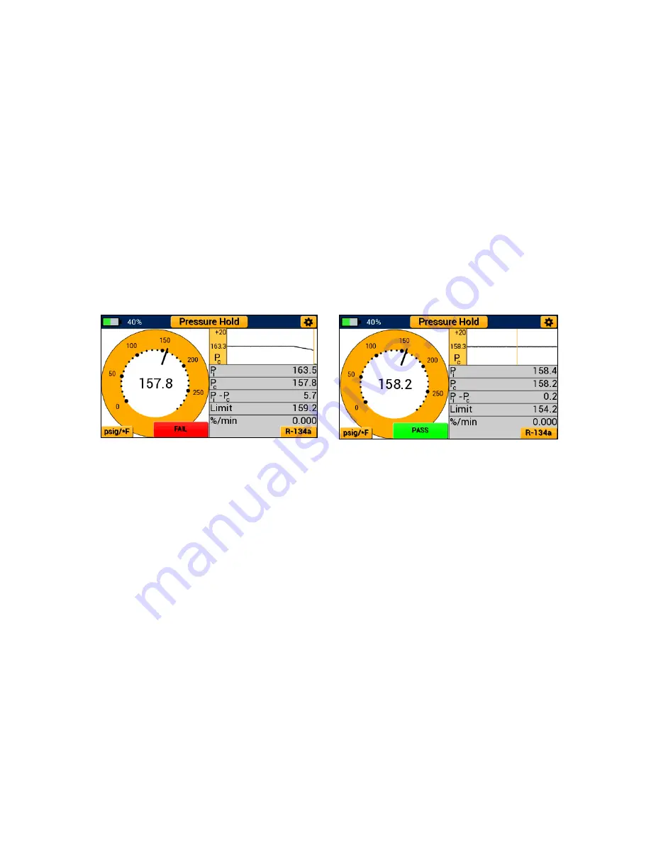
If the system pressure falls below the limit pressure within the test time limits, the P51-870 

TITAN® will display a “FAIL” notice (Figure 24) and the buzzer will sound indicating the test is 

complete. To silence the buzzer, exit the pressure decay test by selecting the modes button. If 

the pressure decay test ends before the system pressure falls below the limit pressure, the device 

will display a “PASS” notice and the buzzer will sound indicating the test is complete (Figure 25).  


Pressure Hold Mode - Pressure Rise Test 

Overview: 

Pressure hold mode can also be used to monitor the system for a rise in vacuum pressure. A 

pressure rise test can be helpful to determine if the system has a leak or there are non-

condensables and refrigerant remaining within the system. The pressure rise test displays the 

current system vacuum pressure (Pvac), the percent change per minute (%/min), the initial 

pressure (Pi), the Limit pressure and test duration.  


Figure 24: Pressure Decay Test - FAIL


Figure 25: Pressure Decay Test - PASS


Summary of Contents for 40870

Page 1: ...ese Instructions do not cover the manifold attached to the instrument For instructions on use of the TITAN 4 Valve Manifold please visit https yellowjacket com product titan 4 valve test and charging...

Page 2: ...des Menu 9 Pressure Temperature Mode 9 Overview 9 Interpreting the Pressure Analog Gauges 10 Interpreting the Pressure and Temperature Line Graphs 10 Operating Pressure Temperature Mode 11 Evacuation...

Page 3: ...e Units 22 Temperature Units 22 Vacuum Units 22 Device Settings Menu 22 Brightness 22 Backlight Timer 22 Auto Off 23 Logging Rate 23 Ch 5 YJACK View App Integration 24 Overview 24 Operation of the YJA...

Page 4: ...oid personal injury or death follow these guidelines Most governments and legal authorities re quire that HVAC technicians be trained and certified in the safe and proper operation of HVAC tools such...

Page 5: ...damaged thermocouple or vacuum sensor could allow an electrical path across the instrument and over wet hoses Keep all interconnected equipment clean organized and in proper condition Do not use the i...

Page 6: ...and release the power button located at bottom center of the display The YJ logo will appear briefly on startup The current firmware version and Serial Number are displayed at the bottom left and righ...

Page 7: ...tions on touchscreen calibration see page 21 Connecting and Using the Temperature Clamps Two 67010 temperature clamps pictured in Figure 6 are supplied with the P51 870 TITAN and can be used to monito...

Page 8: ...distance from the vacuum pump such that it does not disturb the vacuum measurements Interpreting the Battery Life Indicator This instrument utilizes a 2000mAhr rechargeable lithium ion battery It is e...

Page 9: ...s equipped with an adjustable backlight and backlight auto dimming capabilities When the backlight dims during use a touch anywhere on the screen or a quick press of the power button can be used to wa...

Page 10: ...nvention preventing duplicates See Figure 15 for example of stored datalog files Ex 50th week of 2017 with device serial number ending in 127 4th datalog file 750127AD These files cannot be modified w...

Page 11: ...to a larger time increment the LED will not flash blue as often Flashing Red When the device reaches low charge or falls below 10 battery charge the LED will flash red every time a datalog sample is...

Page 12: ...icon in the upper right hand corner Pressure Temperature Mode Overview The P51 870 TITAN Pressure Temperature mode can be used to accurately diagnose and service any system with compatible refrigerant...

Page 13: ...s displayed in a digital format at the center of each blue and red analog gauge respectively Each gauge needle adjusts in real time and can be used to observe fluctuations in pressure as if utilizing...

Page 14: ...e at any time by tapping anywhere within the graph Operating Pressure Temperature Mode While on any modes screen or the modes menu tap the settings icon in the upper right hand corner to access the ge...

Page 15: ...l Settings Button System vacuum pressure is displayed in real time as a digital representation as denoted by Pvac analog as represented by the green analog gauge and a graphical format as a logarithmi...

Page 16: ...ding Use the Target and Hold buttons to set the target vacuum level and vacuum hold timer respectively Pressing each of these buttons will cycle between a range of available values with the last value...

Page 17: ...igerant and non condensables can cause the vacuum level to rise in a system giving a false positive during a leak test when no leak is present Pressure Hold Mode Pressure Decay Test Overview The P51 8...

Page 18: ...ear scale with minor divisions displayed as small dots and major divisions displayed as larger dots respectively The current system pressure is displayed in a digital format at the center of the analo...

Page 19: ...s measured as a percent of the initial system pressure the system can drop before the P51 870 TITAN deems the pressure decay test a failure To adjust the allowable change percent drag the slider bar u...

Page 20: ...will display a FAIL notice Figure 24 and the buzzer will sound indicating the test is complete To silence the buzzer exit the pressure decay test by selecting the modes button If the pressure decay t...

Page 21: ...gital analog vacuum gauge as evacuation mode The pressure rise gauge operates on a logarithmic scale from atmosphere ATM to 0 microns A digital reading and currently selected vacuum units are displaye...

Page 22: ...desired settings have been set select the continue button to advance to the pressure rise test The back button can be used to return to the previous evacuation screen After selecting the continue but...

Page 23: ...gs menus tap on the appropriate button The exit button in the bottom left corner can be used to return to the previous screen at any time Zeroing the Pressure Transducers To ensure accurate pressure r...

Page 24: ...rigerant Settings Menu The refrigerant settings menu shown in Figure 31 can be accessed either by tapping on the Change Refrigerant button in the general settings menu or by tapping the button in the...

Page 25: ...the Device Settings button in the general settings menu To adjust the display brightness tap and drag the slider bar next to brightness until the desired brightness is displayed To adjust the backligh...

Page 26: ...t the logging rate to the lowest possible time interval 1s but this may result in extremely large datalog files making it difficult to analyze the information Be sure to set the logging rate to an app...

Page 27: ...ce Navigate to the YJACK VIEW App and make sure the manifold is powered on The P51 870 TITAN should appear in the available devices menu as the name of the device followed by the serial number Ex YJP5...

Page 28: ...dirty generously soak a soft cloth with warm soapy dish soap water and place the cloth for a couple of minutes over the display to loosen any stubborn dirt Wipe off excess water with a clean less damp...

Page 29: ...acklight Size Approx 7 5 x 8 5 x 4 25 Weight 2 63 lbs Table 7 2 Instrument Specifications Working Pressure 0 700 psia 48 3 bar Pressure Sensing Resolution 0 1 psi 0 1 bar 1 kPa 0 001 MPa 0 01 kg cm 2...

Page 30: ...d Temperature clamp cable damaged Call technical support Temperature clamp jacks damaged Call technical support Clamp not properly attached to system Check clamp connections to system Low Side and Hig...

Page 31: ...28...

Reviews: