EtherAnt II User’s Manual
WARNING
If DC Power is applied while you are attempting to insert the round
connector into the jack, it is possible that, as you rotate the plug in an
effort to find the key, DC power pins will momentarily touch the Ethernet
pins.
If this happens the Ethernet circuitry on the board will blow
.
Any damage caused by this action will not be covered by the factory
warranty and will be a billable repair.
4. Connect the Ethernet cable labeled “To PC or ROUTER” from the Cat 5 DC Power Injector to
your computer or PC. If you connect to a router, switch or hub, make sure you plug the cable into
the WAN/Uplink port, otherwise a cross-over cable or adapter will be needed.
5. Plug the AC Adapter into an AC outlet and connect it to the “DC Power” jack on the Cat 5 DC
Power Injector.
6. Check that the Power and Ethernet LEDs are lit. For –LR models, check that the RX / Power
amplifier LED (green) is also lit.
7. Configure the EtherAnt II Client Adapter using the Client Manager software. (See Section 3 for
detailed information.)
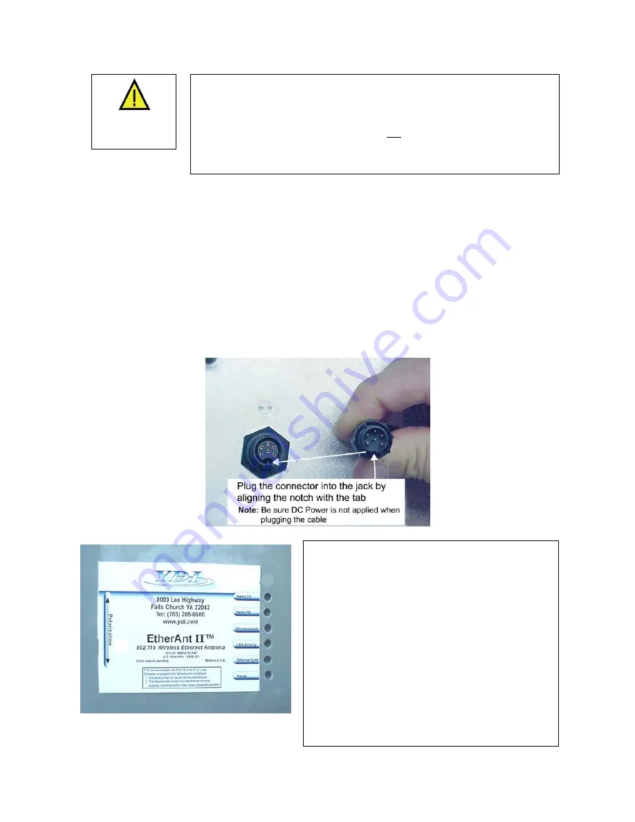
Figure 2.3 – Plugging the Outdoor Ethernet Cable
Figure 2.4 shows the EtherAnt II label located
on the back of the flat panel. Six green LEDs
appear to the right that indicate the status of the
Radio TX, Radio RX, Wireless Link, LAN
Activity, Ethernet Link and Power.
–LR models have two additional amplifier
LEDs. The green LED is for Receive and
Power: it glows steady on when DC power is
applied and flashes when the unit is in receive
mode. The red LED is for Transmit and flashes
when the unit is in transm
it mode.
e
The arrow to the left indicates the polarization
of the antenna. Based upon the direction of th
arrow, the antenna in this example is vertically
polarized.
Figure 2.4 – EtherAnt
II
Label and LEDs
Version 3.3
Page 7
March 2003
Summary of Contents for EtherAnt II
Page 1: ...Version 3 3 March 2003 ...
Page 27: ...EtherAnt II User s Manual Version 3 3 Page 24 March 2003 ...
Page 28: ......


